

Category: Knowledge
-
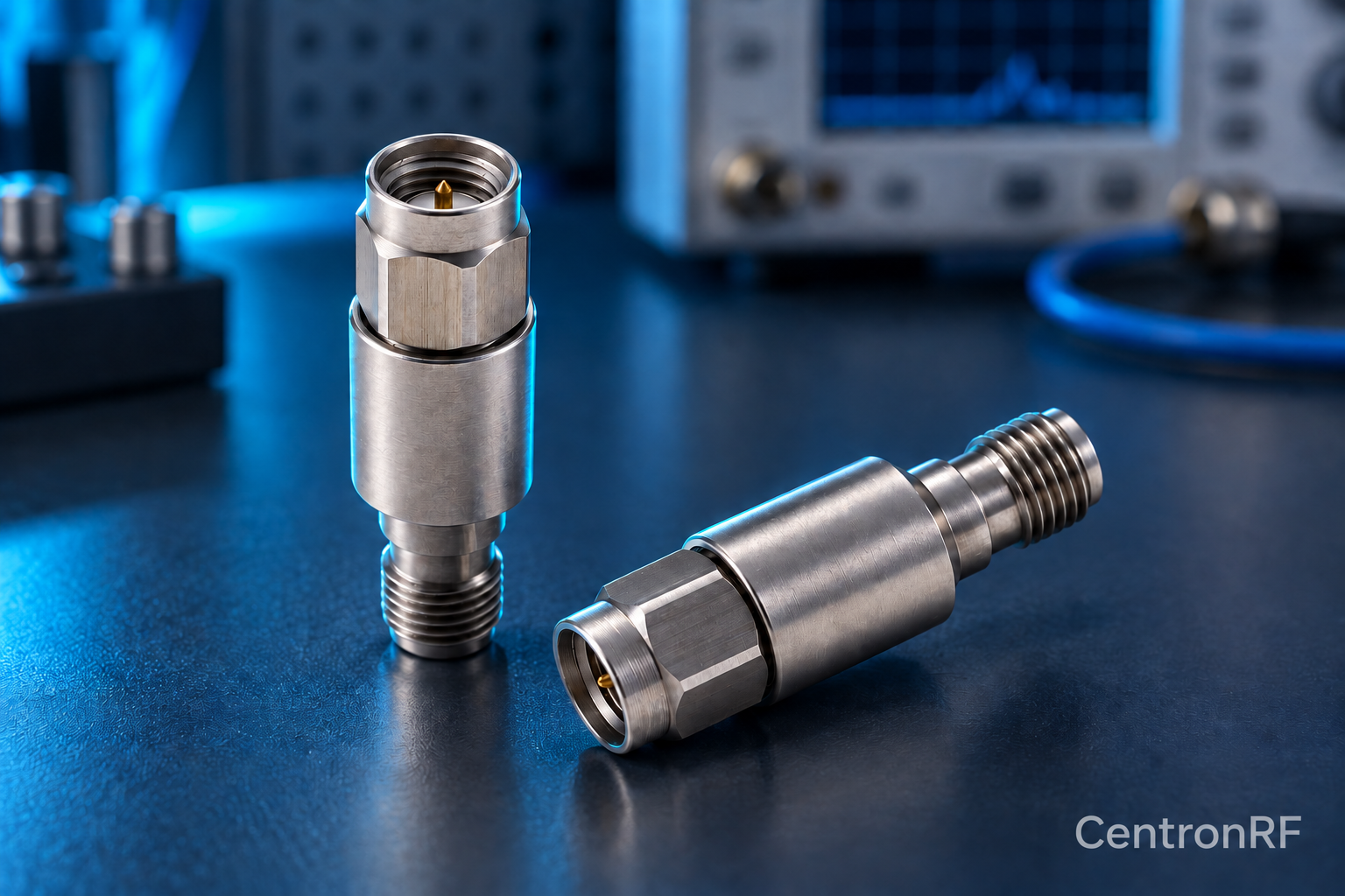
External Versus Internal Spectrum Analyzer Attenuation
External attenuation reduces power before the analyzer connector. Internal attenuation adjusts…
-
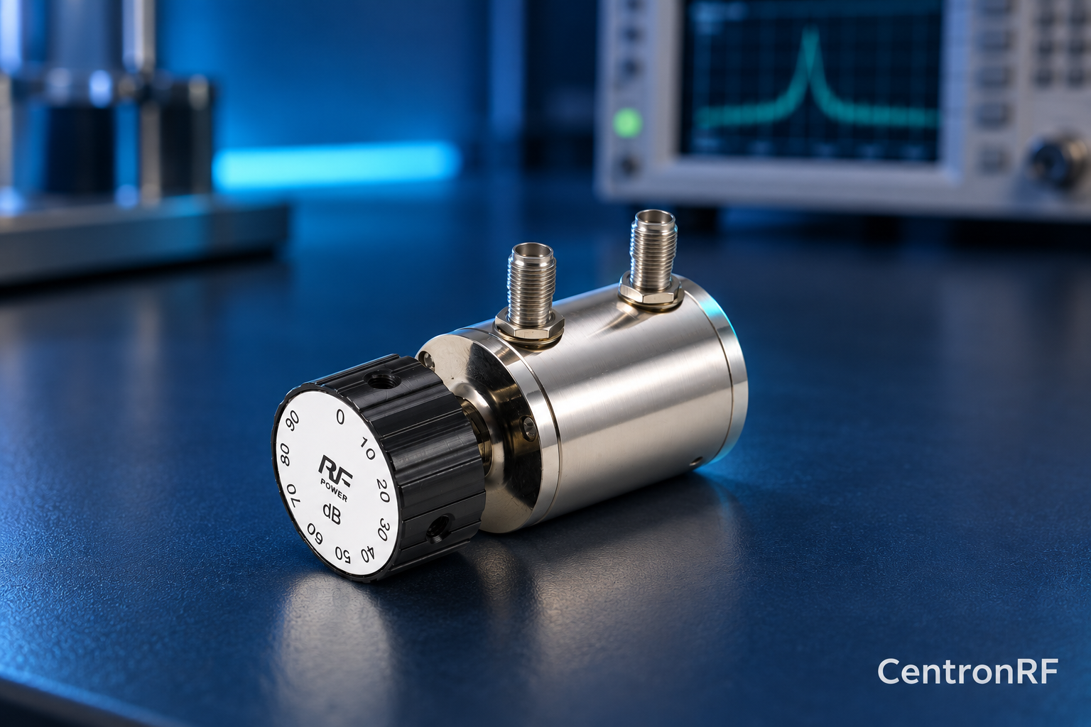
Why Step Attenuator Accuracy Changes with Frequency
Parasitic capacitance, inductance, connectors and switch paths can make actual attenuation…
-
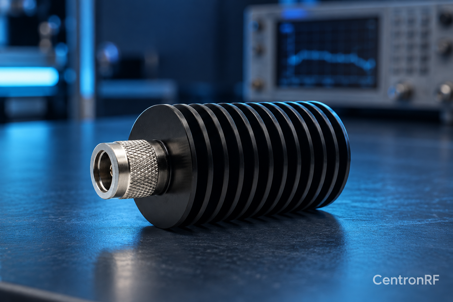
Dummy Load Versus Attenuator: The Port Difference
A dummy load absorbs the signal at a terminating port; an…
-
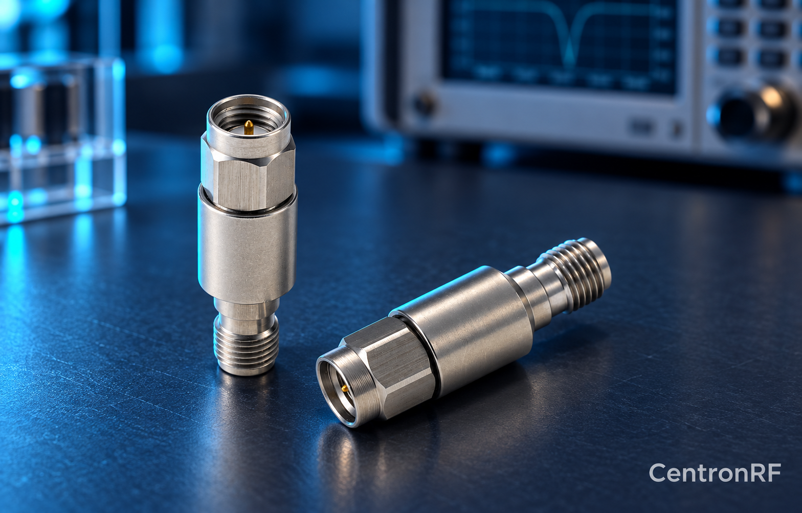
How to Choose a DC Block for an RF Instrument
Choose a DC block from the instrument’s permitted DC input, the…
-
Documenting a DC Block Requirement for Procurement
Specify construction type, impedance, connector genders, RF passband, maximum insertion loss,…
-
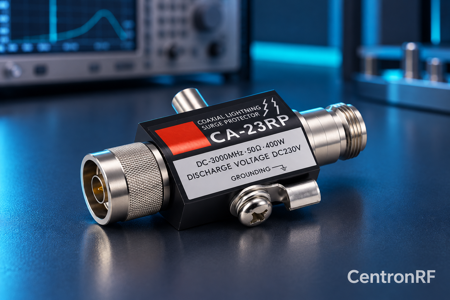
Replacing a Surge Protector’s Discharge Element
Replace an element only when the protector is explicitly designed for…
-
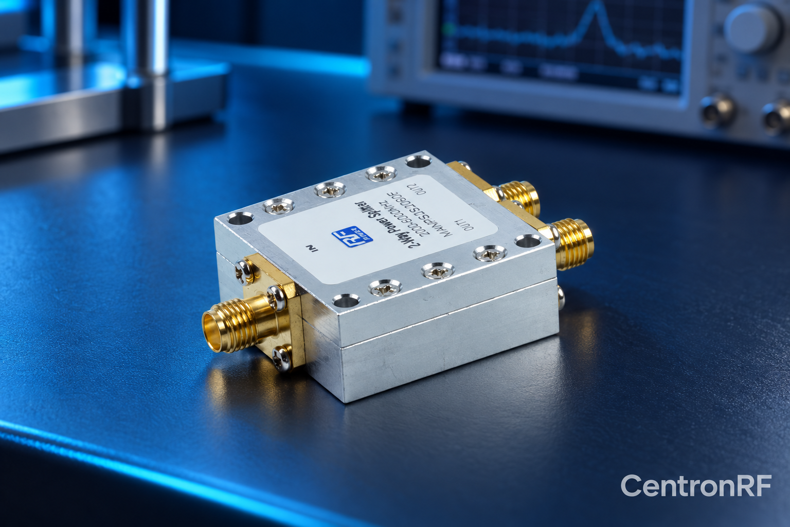
RF Divider Input Match and Load Conditions
A divider’s input match depends on its design and the loads…
-
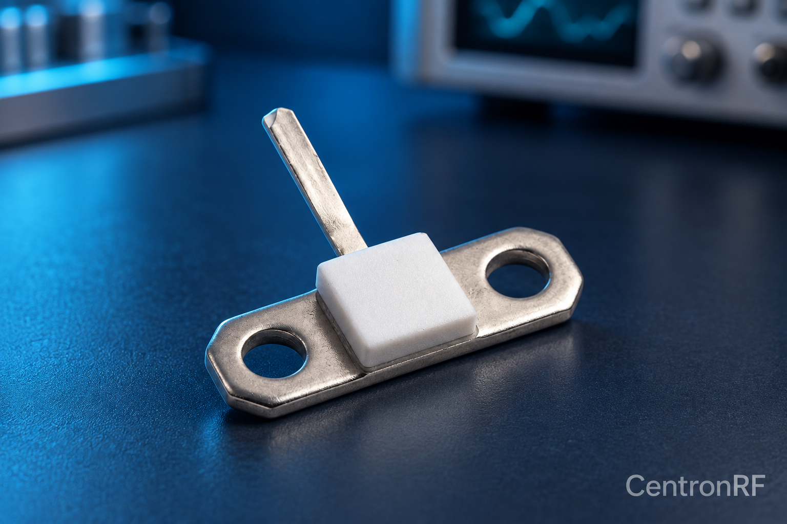
RF Resistor Voltage and Current Calculations
For a purely resistive matched condition, RMS voltage is the square…
-
50-Ohm and 75-Ohm Connectors: Mechanical Fit Is Not Enough
Connectors and cables must match the intended system impedance. Some interfaces…
-
How to Label an RF Test Cable Assembly
Label the assembly with an identifier and retain its interfaces, impedance,…