


Label the assembly with an identifier and retain its interfaces, impedance, frequency range and relevant ratings in the test record. Add calibration data where applicable.
How it works in practice
Avoid relying on cable color alone. Document loss and phase corrections at the frequencies used, and note inspection or calibration dates. A replacement cable can change the reference plane and results. Keep labels clear without obstructing connectors or forcing sharp bends.
Example and interpretation
A record for cable C3 can identify its 2.4 GHz loss correction and which end belongs at the instrument.
Checks before use
- Assign an identifier
- Record ratings and interfaces
- Store measured corrections
- Track replacement and inspection
Important limit
Do not apply one cable's calibration to an unverified replacement.
Related Centron RF product
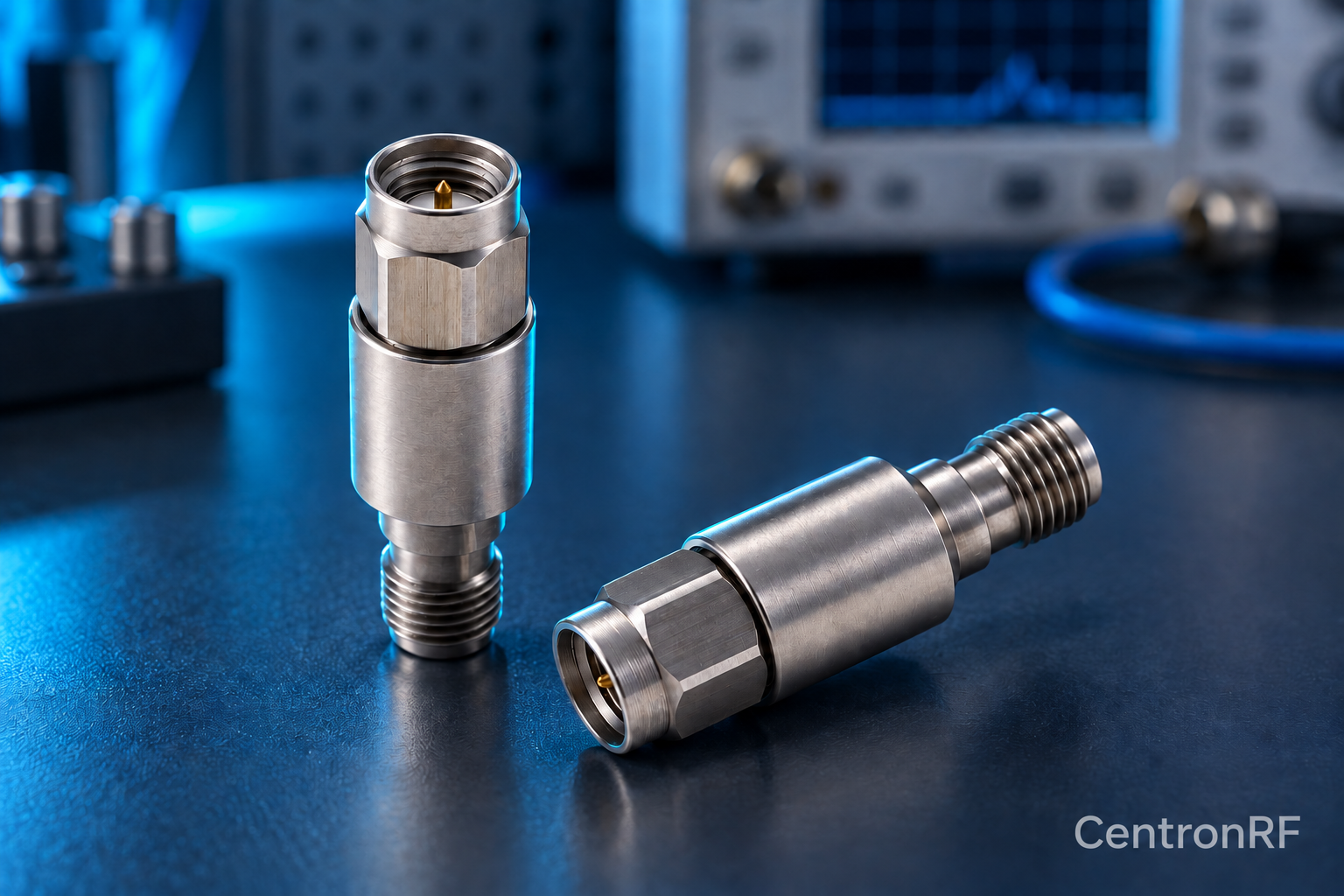
N-type fixed attenuator for a compatible RF path. Use a product page to check both connector interfaces, nominal impedance and model-specific band and power requirements. The connector family alone cannot establish a component’s total RF capability.
Further reading
Rohde & Schwarz: Impedance, VSWR and Return Loss. This background reference explains general principles; the selected Centron RF model’s datasheet governs its own ratings.
Related guides
Educational guide. Numerical examples use the stated assumptions and are not test results for a supplied unit.