


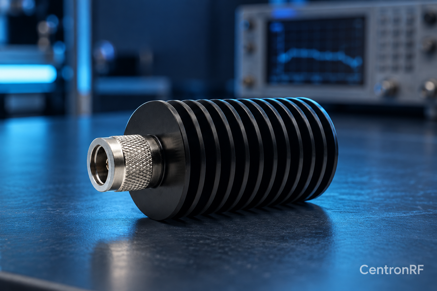
A dummy load absorbs the signal at a terminating port; an attenuator reduces a signal while passing it to another port. They serve different positions in a test path.
How it works in practice
Use a load where the path must end in its intended impedance. Use an attenuator where a downstream device needs a lower signal level. An attenuator's output generally needs a suitable termination for its specified behavior, so leaving it open can change the result.
Example and interpretation
An amplifier can feed a load for power testing, or a rated attenuator followed by a measuring receiver when the complete path can safely handle the power.
Checks before use
- Draw the signal path
- Identify its final termination
- Identify required level reduction
- Rate each component
Important limit
A two-port pad with an open output is not equivalent to a properly terminated load.
Related Centron RF product
N-type 50 W 6 GHz dummy load. The linked N-type load is a starting point for comparing impedance, bandwidth, power and mechanical fit. Confirm the exact connector option and current thermal conditions before using any load near its rated power.
Further reading
Rohde & Schwarz: VSWR and Return Loss. This background reference explains general principles; the selected Centron RF model’s datasheet governs its own ratings.
Related guides
Educational guide. Numerical examples use the stated assumptions and are not test results for a supplied unit.