


Choose a DC block from the instrument's permitted DC input, the expected cable bias and the required RF band. Check maximum voltage as carefully as frequency.
How it works in practice
Include polarity where relevant, startup transients and the insertion loss at the lowest signal frequency. A block that protects against steady DC may not be rated for a surge event. Check its RF power and capacitor stress limits. Keep the protected input within all instrument specifications.
Example and interpretation
A path carrying 12 V bias needs a documented block voltage rating above the actual worst-case differential voltage, with appropriate margin.
Checks before use
- Read instrument DC limits
- Identify worst-case bias
- Verify voltage and RF ratings
- Measure insertion loss
Important limit
A frequency rating alone does not establish instrument protection.
Related Centron RF product
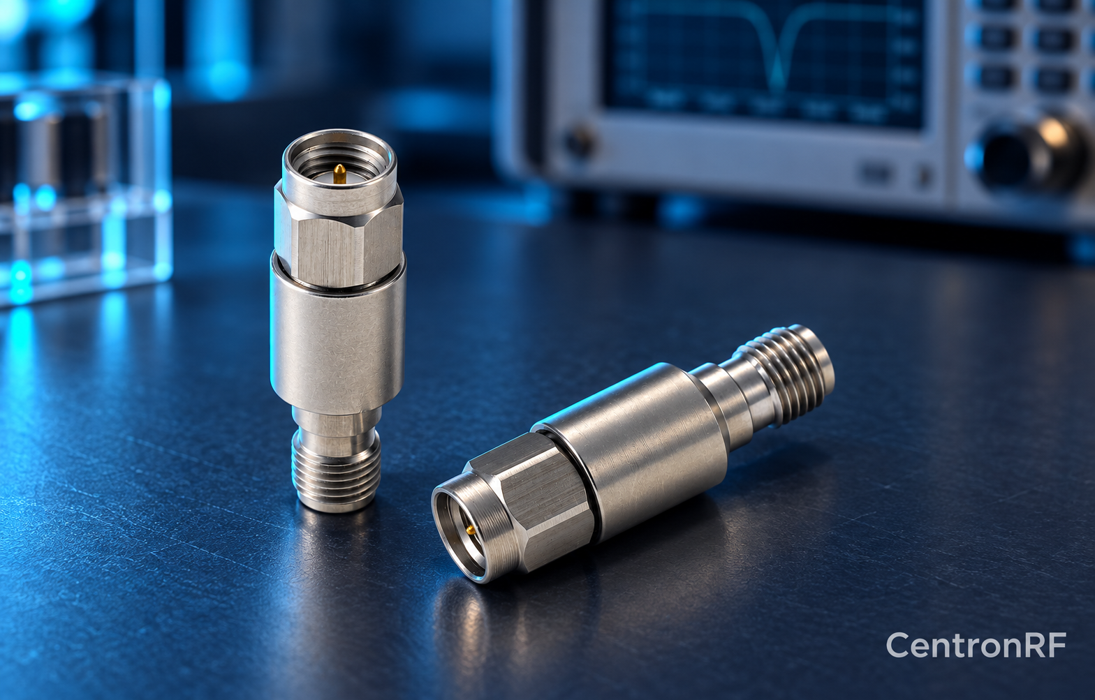
SMA DC block listed for 8 GHz applications. The linked SMA block gives an upper-frequency reference. Confirm its lower passband limit, working voltage, RF power and whether it blocks the inner, outer or both conductors. A catalog range starting with DC should not be interpreted as DC transmission.
Further reading
Mini-Circuits: DC Block Specifications. This background reference explains general principles; the selected Centron RF model’s datasheet governs its own ratings.
Related guides
Educational guide. Numerical examples use the stated assumptions and are not test results for a supplied unit.