


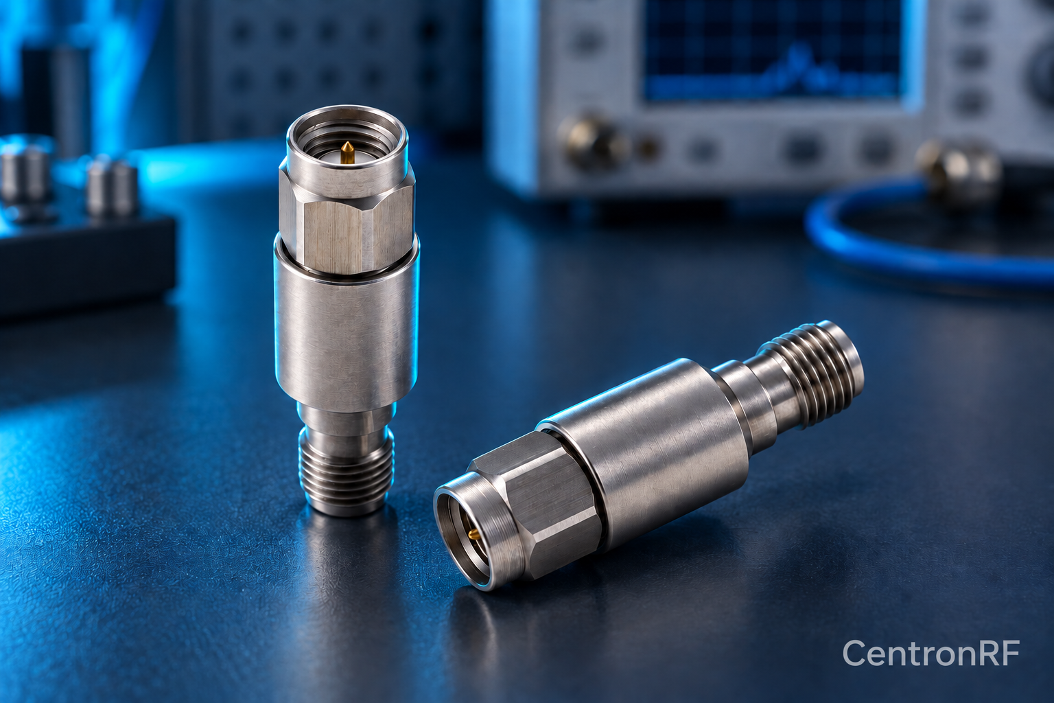
Power handling depends on frequency, voltage, current, mismatch and thermal conditions across the whole assembly. Verify exact component ratings.
How it works in practice
A larger connector can have mechanical advantages, but the internal resistor or capacitor may be the limiting element. Cable temperature and standing-wave peaks can also matter. Use continuous and pulse limits for the actual parts, especially near high-power transmitters.
Example and interpretation
A small internal DC-block capacitor may limit a path even when its external connector appears robust.
Checks before use
- Check every component
- Include mismatch and peaks
- Check thermal conditions
- Confirm pulse limits
Important limit
Do not infer watts from connector appearance.
Related Centron RF product
N-type fixed attenuator for a compatible RF path. Use a product page to check both connector interfaces, nominal impedance and model-specific band and power requirements. The connector family alone cannot establish a component’s total RF capability.
Further reading
Rohde & Schwarz: Impedance, VSWR and Return Loss. This background reference explains general principles; the selected Centron RF model’s datasheet governs its own ratings.
Related guides
Educational guide. Numerical examples use the stated assumptions and are not test results for a supplied unit.