


An RF cable delays the signal, so electrical phase depends on frequency, length and propagation velocity. Equal physical lengths do not guarantee identical electrical lengths.
How it works in practice
Cable construction, connectors and tolerances affect delay. In coherent systems, measure or specify phase matching at the intended frequency and conditions. Bending and temperature can alter some cables' phase. Use calibrated corrections when practical.
Example and interpretation
At a velocity factor of 0.7, a 1 m cable delay is approximately 4.76 ns; at 1 GHz that is multiple phase rotations.
Checks before use
- Identify velocity factor
- Estimate delay
- Measure relative phase
- Control routing and temperature
Important limit
Do not compare phase from physical ruler measurements alone.
Related Centron RF product
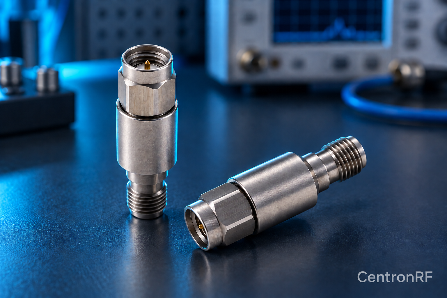
N-type fixed attenuator for a compatible RF path. Use a product page to check both connector interfaces, nominal impedance and model-specific band and power requirements. The connector family alone cannot establish a component’s total RF capability.
Further reading
Rohde & Schwarz: Impedance, VSWR and Return Loss. This background reference explains general principles; the selected Centron RF model’s datasheet governs its own ratings.
Related guides
Educational guide. Numerical examples use the stated assumptions and are not test results for a supplied unit.