


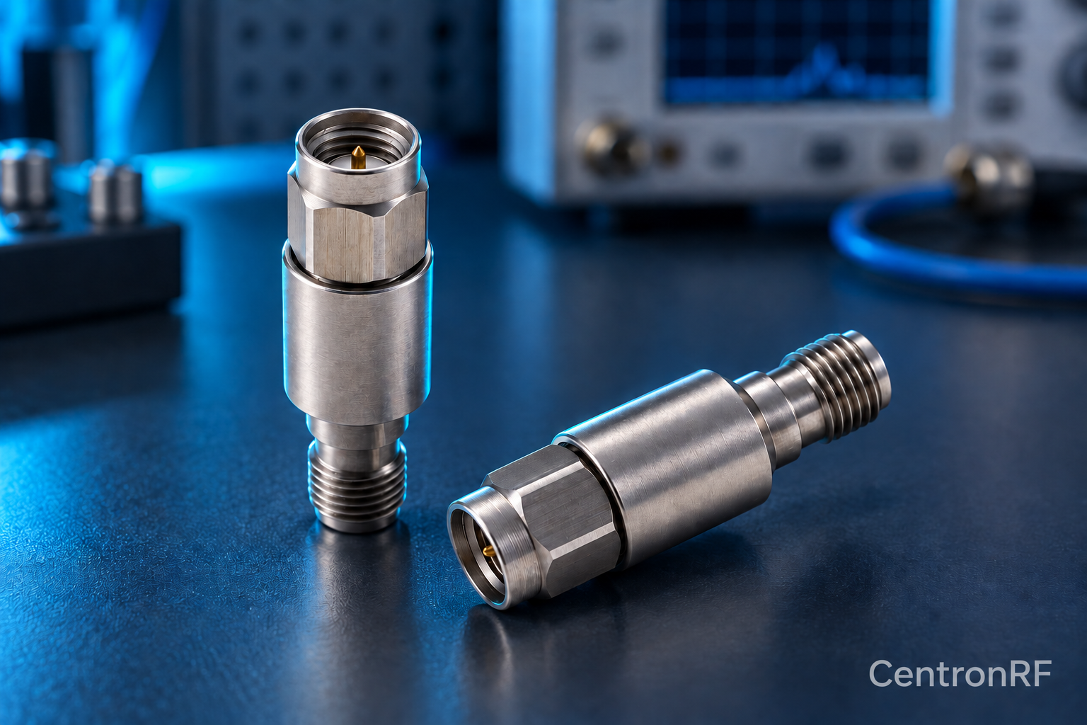
Adapters add a transition with its own loss, reflection and frequency limits. Include them in the path budget and calibration when accuracy matters.
How it works in practice
Minimize unnecessary adapter chains and support their mechanical weight. A connector-compatible adapter may not cover the required band or power. Keep calibration planes consistent after adding or removing one. Inspect center contacts and mating surfaces before connection.
Example and interpretation
A new adapter outside the calibrated plane can change the measured loss and phase even if it appears small.
Checks before use
- Check adapter ratings
- Inspect mating surfaces
- Include it in calibration
- Support the assembled chain
Important limit
Do not treat an adapter as electrically invisible.
Related Centron RF product
N-type fixed attenuator for a compatible RF path. Use a product page to check both connector interfaces, nominal impedance and model-specific band and power requirements. The connector family alone cannot establish a component’s total RF capability.
Further reading
Rohde & Schwarz: Impedance, VSWR and Return Loss. This background reference explains general principles; the selected Centron RF model’s datasheet governs its own ratings.
Related guides
Educational guide. Numerical examples use the stated assumptions and are not test results for a supplied unit.