


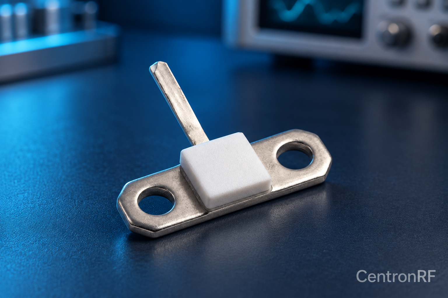
An RF resistor is designed and characterized for high-frequency behavior; an ordinary resistor may have unsuitable parasitics for the same application.
How it works in practice
Compare impedance, mounting, frequency behavior and power conditions rather than only the DC resistance. Lead length, package geometry and the surrounding circuit can alter performance. Even an RF-rated element needs the intended layout and thermal arrangement.
Example and interpretation
A 50-ohm leaded resistor and a 50-ohm RF flange resistor can have different impedance at several GHz.
Checks before use
- Identify operating frequency
- Compare package parasitics
- Check RF data
- Evaluate installed match
Important limit
Equal ohmmeter readings do not prove RF interchangeability.
Related Centron RF product
50-ohm 10 W thick-film RF resistor. The linked resistor is listed as 50 ohms, 10 W and 4 GHz. Request the recommended mounting, heatsink, derating, tolerance and pulse conditions; those determine whether it is suitable for the intended circuit.
Further reading
Vishay: Resistor Technical FAQ. This background reference explains general principles; the selected Centron RF model’s datasheet governs its own ratings.
Related guides
Educational guide. Numerical examples use the stated assumptions and are not test results for a supplied unit.