


Attenuation flatness describes variation in loss across a frequency range. It determines how closely one correction value represents a broadband signal path.
How it works in practice
A component may remain within its usable frequency range while its loss varies enough to affect a measurement. For swept or modulated signals, characterize loss at relevant frequency points and apply a frequency-dependent correction where needed. Include cables and adapters if the correction refers to the full path.
Example and interpretation
A path with 20.1 dB loss at one frequency and 20.8 dB at another needs different corrections if a 0.7 dB difference matters to the result.
Checks before use
- Define the measurement band
- Measure the complete path
- Build a correction table
- Check the interpolation error
Important limit
A maximum frequency rating does not guarantee perfectly flat attenuation.
Related Centron RF product
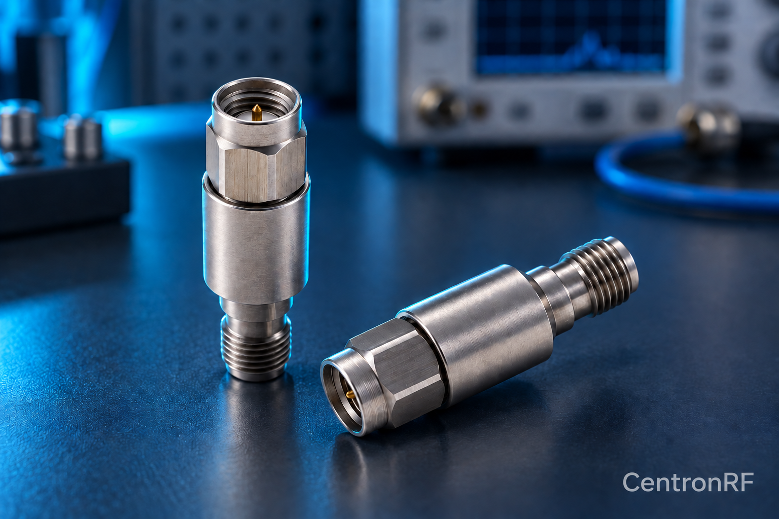
SMA 5 W 6 GHz fixed attenuator. The SMA 5 W model is listed as a 50-ohm fixed attenuator with a DC–6 GHz range. Select an available attenuation option and verify the current tolerance, cooling conditions and pulse limits for your application.
Further reading
Keysight: Spectrum Analysis Basics. This background reference explains general principles; the selected Centron RF model’s datasheet governs its own ratings.
Related guides
- How an Attenuator Can Reduce RF Mismatch Effects
- Attenuators Before an LNA: Protection Versus Sensitivity
Educational guide. Numerical examples use the stated assumptions and are not test results for a supplied unit.