


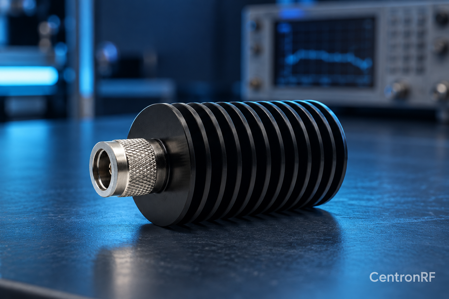
Match the termination's nominal impedance to the transmission system. Connecting 50-ohm and 75-ohm components creates a mismatch even when connectors fit.
How it works in practice
Impedance describes the relationship between RF voltage and current in the intended system. A mismatch reflects part of the incident wave and may affect level accuracy. RF lab equipment commonly uses 50 ohms, while some video and cable systems use 75 ohms; always verify the actual interface.
Example and interpretation
For ideal real impedances of 50 and 75 ohms, the reflection coefficient magnitude is 0.2 and VSWR is 1.5.
Checks before use
- Identify the system impedance
- Check each adapter
- Use the correct termination
- Measure match over the band
Important limit
Connector appearance alone cannot identify impedance.
Related Centron RF product
N-type 50 W 6 GHz dummy load. The linked N-type load is a starting point for comparing impedance, bandwidth, power and mechanical fit. Confirm the exact connector option and current thermal conditions before using any load near its rated power.
Further reading
Rohde & Schwarz: VSWR and Return Loss. This background reference explains general principles; the selected Centron RF model’s datasheet governs its own ratings.
Related guides
Educational guide. Numerical examples use the stated assumptions and are not test results for a supplied unit.