


Review power, pulses, mounting and matching before assigning a cause to a failed resistor. Several stresses can produce similar visible damage.
How it works in practice
Record source levels, duty cycle, ambient conditions and the state of surrounding equipment. Inspect solder joints and heat paths after power is removed. A failure can arise from transient overload or an inadequate thermal interface even when nominal average power appears acceptable.
Example and interpretation
A combiner resistor damaged during a source fault may have faced imbalance stress absent from the normal operating budget.
Checks before use
- Preserve operating records
- Check fault states
- Inspect assembly
- Compare with model limits
Important limit
Do not claim a manufacturing defect solely from a burnt appearance.
Related Centron RF product
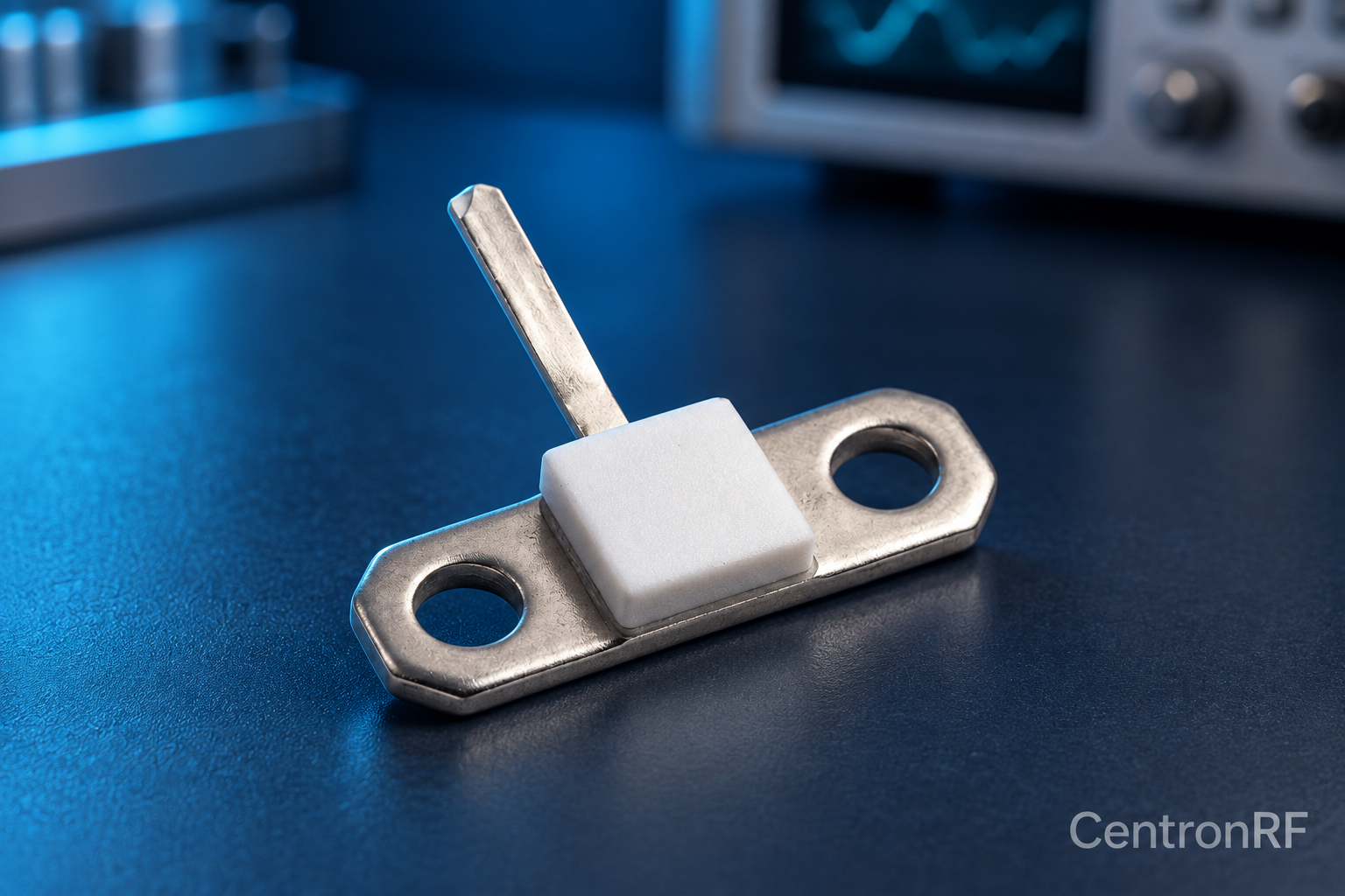
50-ohm 10 W thick-film RF resistor. The linked resistor is listed as 50 ohms, 10 W and 4 GHz. Request the recommended mounting, heatsink, derating, tolerance and pulse conditions; those determine whether it is suitable for the intended circuit.
Further reading
Vishay: Resistor Technical FAQ. This background reference explains general principles; the selected Centron RF model’s datasheet governs its own ratings.
Related guides
Educational guide. Numerical examples use the stated assumptions and are not test results for a supplied unit.