


Settling time allows the source, receiver and measurement system to reach a stable state after an attenuation change. Mechanical selection alone does not guarantee immediate valid data.
How it works in practice
Automatic gain control, averaging and detector filters can delay the observed response. Choose a delay based on the slowest relevant part of the system and verify it experimentally. Avoid assigning a universal settling time when the attenuator or receiver documentation does not provide one.
Example and interpretation
A receiver with a long AGC recovery interval can show a transient level after a 20 dB change even when the RF switch has stopped moving.
Checks before use
- Identify AGC and averaging settings
- Observe the transient
- Choose a justified delay
- Log results only after settling
Important limit
Do not assume the first displayed reading after switching is the final level.
Related Centron RF product
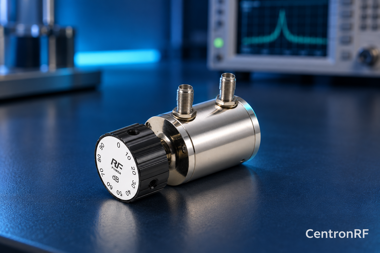
SMA rotary attenuator with 10 dB steps. The linked rotary model lists 0–90 dB adjustment in 10 dB steps, 50-ohm impedance and a DC–6 GHz band. Its listed continuous input is 2 W; obtain explicit switching and pulse limits before applying those stresses.
Further reading
Keysight: Accurate Network Measurements. This background reference explains general principles; the selected Centron RF model’s datasheet governs its own ratings.
Related guides
- Selecting a Rotary Attenuator for a Purchase Specification
- How to Store and Handle a Mechanical RF Attenuator
Educational guide. Numerical examples use the stated assumptions and are not test results for a supplied unit.