


Check connections and measurement stability before attributing an erratic result to the rotary attenuator. Then test the suspect state under controlled conditions.
How it works in practice
Inspect mating surfaces, cable strain and connector tightness. Compare repeated readings at zero and nearby states without moving cables. A fault isolated to one dial position suggests a different cause from fluctuation at every position. Remove questionable hardware from critical measurements until its performance is verified.
Example and interpretation
If all states drift together, investigate source or detector stability; if only one state jumps, investigate that switch path.
Checks before use
- Check cables and interfaces
- Stabilize source and detector
- Repeat adjacent states
- Compare with a known-good path
Important limit
Avoid applying lubricant or cleaning fluid inside a switch unless the manufacturer specifies it.
Related Centron RF product
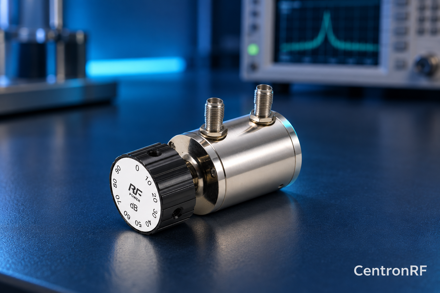
SMA rotary attenuator with 10 dB steps. The linked rotary model lists 0–90 dB adjustment in 10 dB steps, 50-ohm impedance and a DC–6 GHz band. Its listed continuous input is 2 W; obtain explicit switching and pulse limits before applying those stresses.
Further reading
Keysight: Accurate Network Measurements. This background reference explains general principles; the selected Centron RF model’s datasheet governs its own ratings.
Related guides
- How to Store and Handle a Mechanical RF Attenuator
- Step Attenuator Calibration Records: What to Include
Educational guide. Numerical examples use the stated assumptions and are not test results for a supplied unit.