


A load's frequency rating identifies the band over which specified RF performance applies. It is not a universal promise of identical match at all frequencies.
How it works in practice
Look for the matching limit associated with the band and any connector constraints. A DC resistance test checks only one aspect of the device. If your test includes harmonics, consider whether those frequencies also fall within the load's specified operating range.
Example and interpretation
A 3 GHz carrier can produce a 6 GHz second harmonic; the complete measurement path needs appropriate harmonic-frequency behavior.
Checks before use
- List carrier and relevant harmonics
- Check the specified band
- Review VSWR limits
- Verify adapters and cables
Important limit
Do not extend the published band solely because the connector supports a higher frequency.
Related Centron RF product
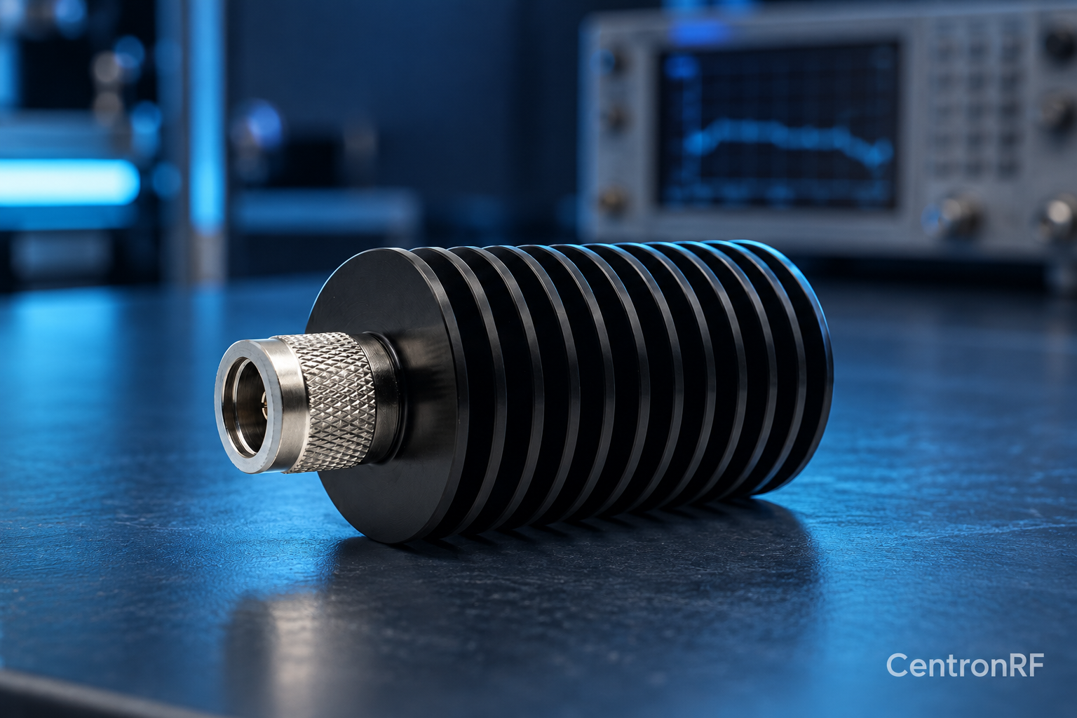
N-type 50 W 6 GHz dummy load. The linked N-type load is a starting point for comparing impedance, bandwidth, power and mechanical fit. Confirm the exact connector option and current thermal conditions before using any load near its rated power.
Further reading
Rohde & Schwarz: VSWR and Return Loss. This background reference explains general principles; the selected Centron RF model’s datasheet governs its own ratings.
Related guides
Educational guide. Numerical examples use the stated assumptions and are not test results for a supplied unit.