


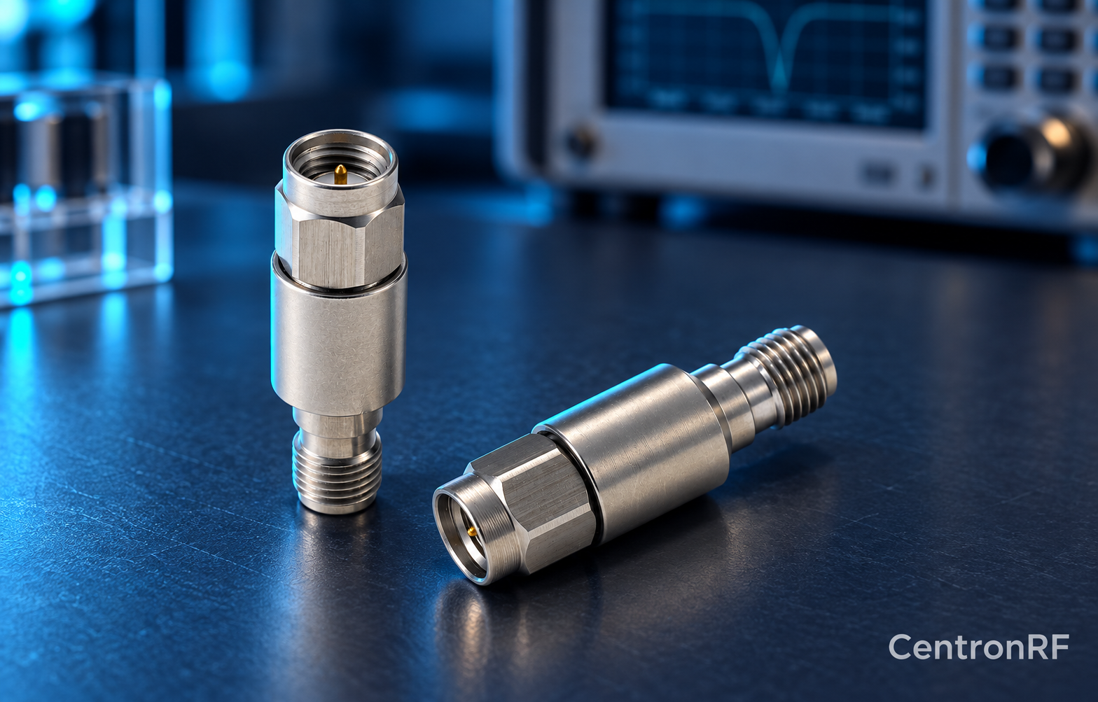
Measure a DC block's RF transmission and reflection with a calibrated VNA over the intended passband. Protect the VNA from any external bias before connection.
How it works in practice
Test the block disconnected from powered equipment unless the setup is explicitly designed for biased measurements. Calibrate to the appropriate connector planes, then examine S21 and S11. Use a frequency span that includes the relevant lower edge and operating band.
Example and interpretation
A sweep can reveal rising loss near the lower band limit that a single high-frequency point would miss.
Checks before use
- Remove external DC
- Calibrate the connection planes
- Sweep transmission and reflection
- Record the exact model and configuration
Important limit
Do not connect a biased cable directly to a VNA input without verified protection.
Related Centron RF product
SMA DC block listed for 8 GHz applications. The linked SMA block gives an upper-frequency reference. Confirm its lower passband limit, working voltage, RF power and whether it blocks the inner, outer or both conductors. A catalog range starting with DC should not be interpreted as DC transmission.
Further reading
Mini-Circuits: DC Block Specifications. This background reference explains general principles; the selected Centron RF model’s datasheet governs its own ratings.
Related guides
Educational guide. Numerical examples use the stated assumptions and are not test results for a supplied unit.