


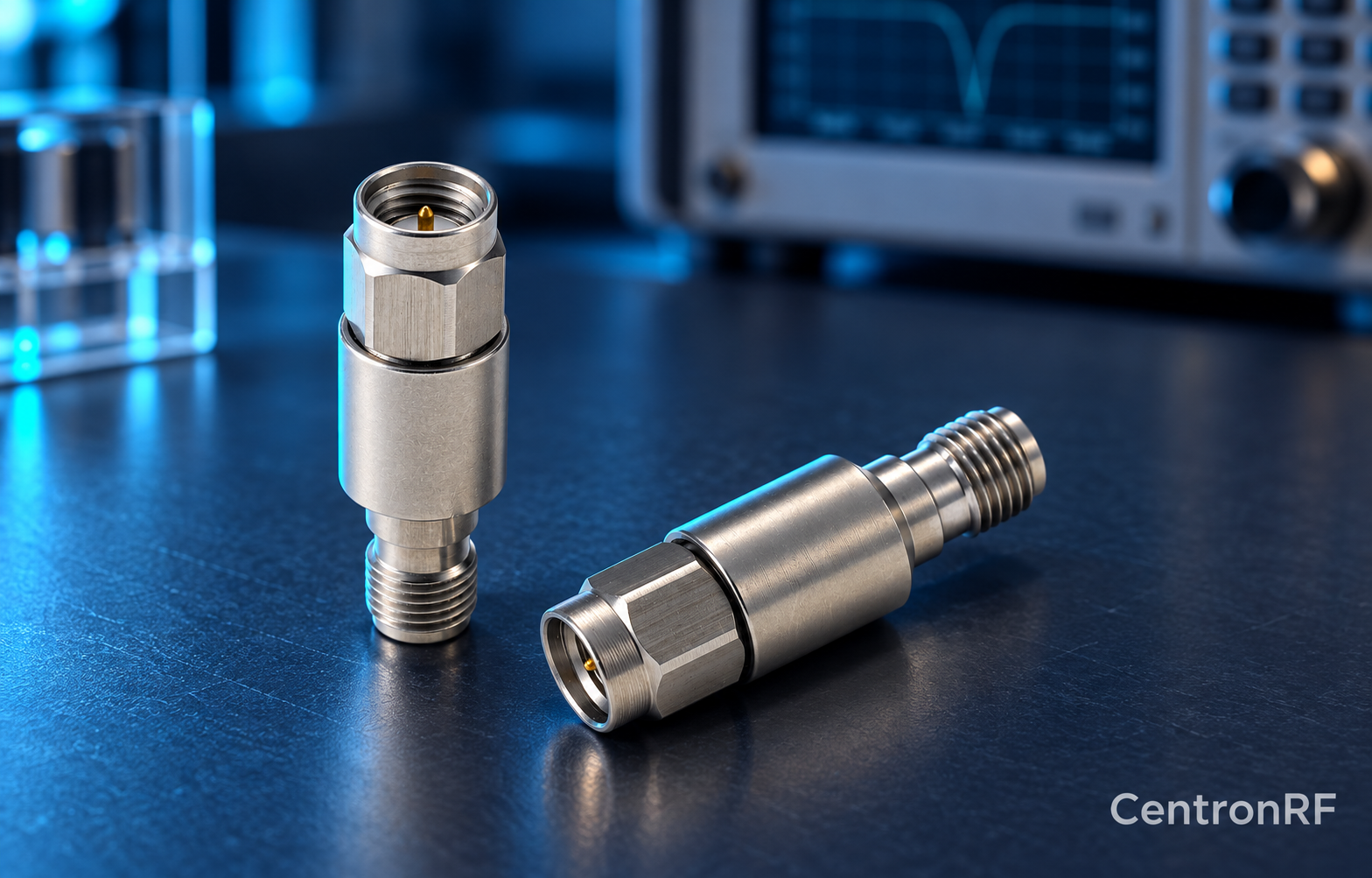
An attenuator lowers RF level; a DC block interrupts specified DC continuity. A measurement chain may need both, with ratings appropriate to their positions.
How it works in practice
Check whether the attenuator passes DC and whether applied bias stresses its resistors. Place a suitably rated block before any component that must not receive the bias. Then calculate the downstream RF level using the measured losses of both devices. The best order depends on DC and RF stress.
Example and interpretation
A 10 dB pad plus a block with 0.3 dB measured loss gives approximately 10.3 dB total path loss at that frequency.
Checks before use
- Map DC continuity
- Rate each component's input
- Choose an appropriate order
- Calibrate the full path
Important limit
Do not assume resistive attenuation safely removes cable bias.
Related Centron RF product
SMA DC block listed for 8 GHz applications. The linked SMA block gives an upper-frequency reference. Confirm its lower passband limit, working voltage, RF power and whether it blocks the inner, outer or both conductors. A catalog range starting with DC should not be interpreted as DC transmission.
Further reading
Mini-Circuits: DC Block Specifications. This background reference explains general principles; the selected Centron RF model’s datasheet governs its own ratings.
Related guides
Educational guide. Numerical examples use the stated assumptions and are not test results for a supplied unit.