


Choose a power sensor and protective path that keep the sensor within its specified measurement and damage ranges. Include waveform and frequency requirements.
How it works in practice
Average, peak and envelope measurements need appropriate sensor capability. An attenuator extends high-level measurement only if its loss is known and it can handle the source. Correct the sensor reading to the desired plane. Include calibration-factor and mismatch contributions in uncertainty.
Example and interpretation
A sensor reading of 0 dBm after a measured 20.2 dB path corresponds to approximately 20.2 dBm at the upstream reference plane.
Checks before use
- Check sensor limits
- Select rated attenuation
- Use frequency corrections
- Report the reference plane
Important limit
Do not apply an average-power sensor reading as a measured peak value.
Related Centron RF product
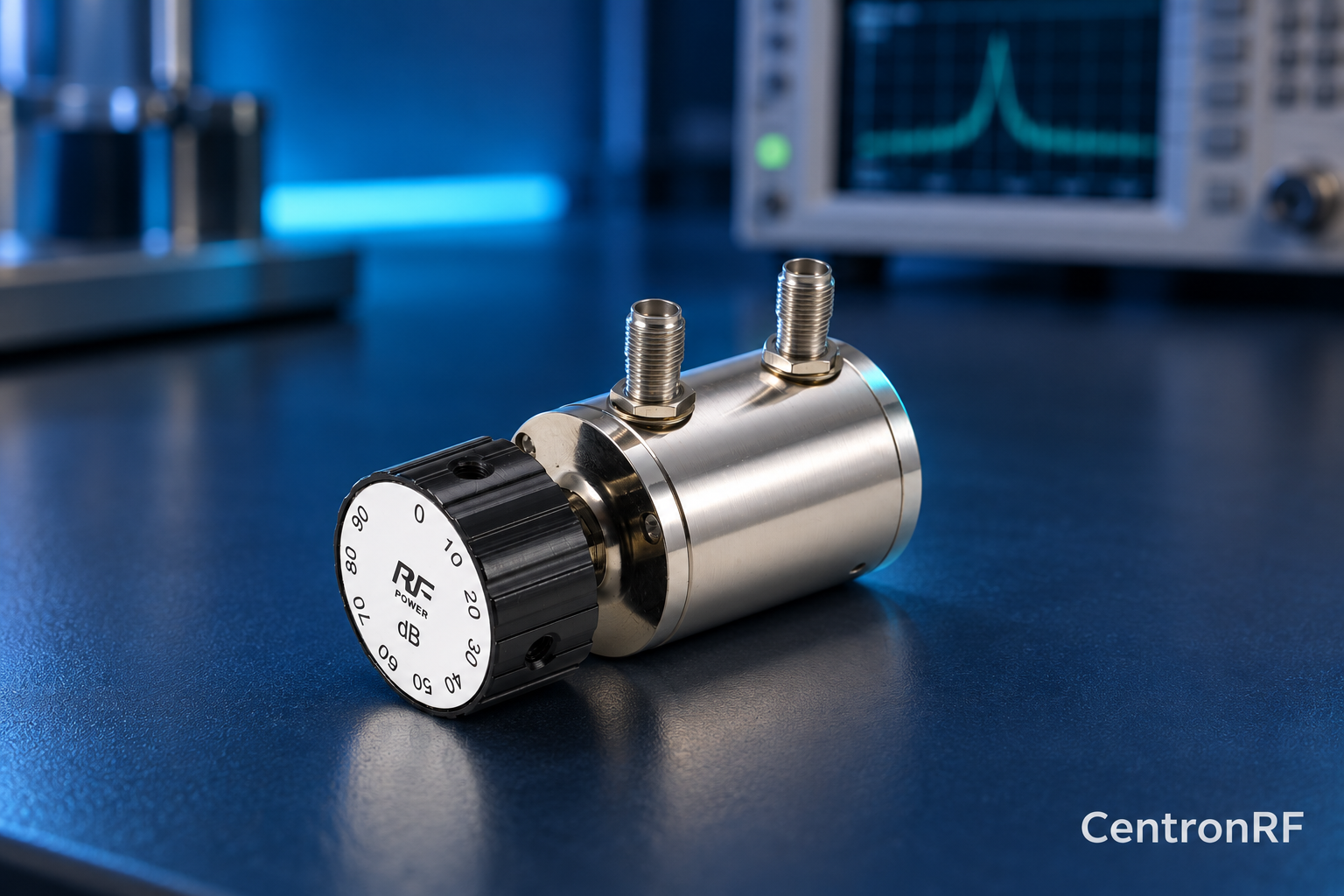
SMA rotary attenuator with 1 dB steps. The linked fine-step unit lists 0–10 dB in 1 dB increments. It can be considered for controlled level changes within its ratings. Dial resolution does not establish traceable accuracy; calibrate the assembled path as required.
Further reading
Keysight: Fundamentals of RF and Microwave Power Measurements. This background reference explains general principles; the selected Centron RF model’s datasheet governs its own ratings.
Related guides
Educational guide. Numerical examples use the stated assumptions and are not test results for a supplied unit.