


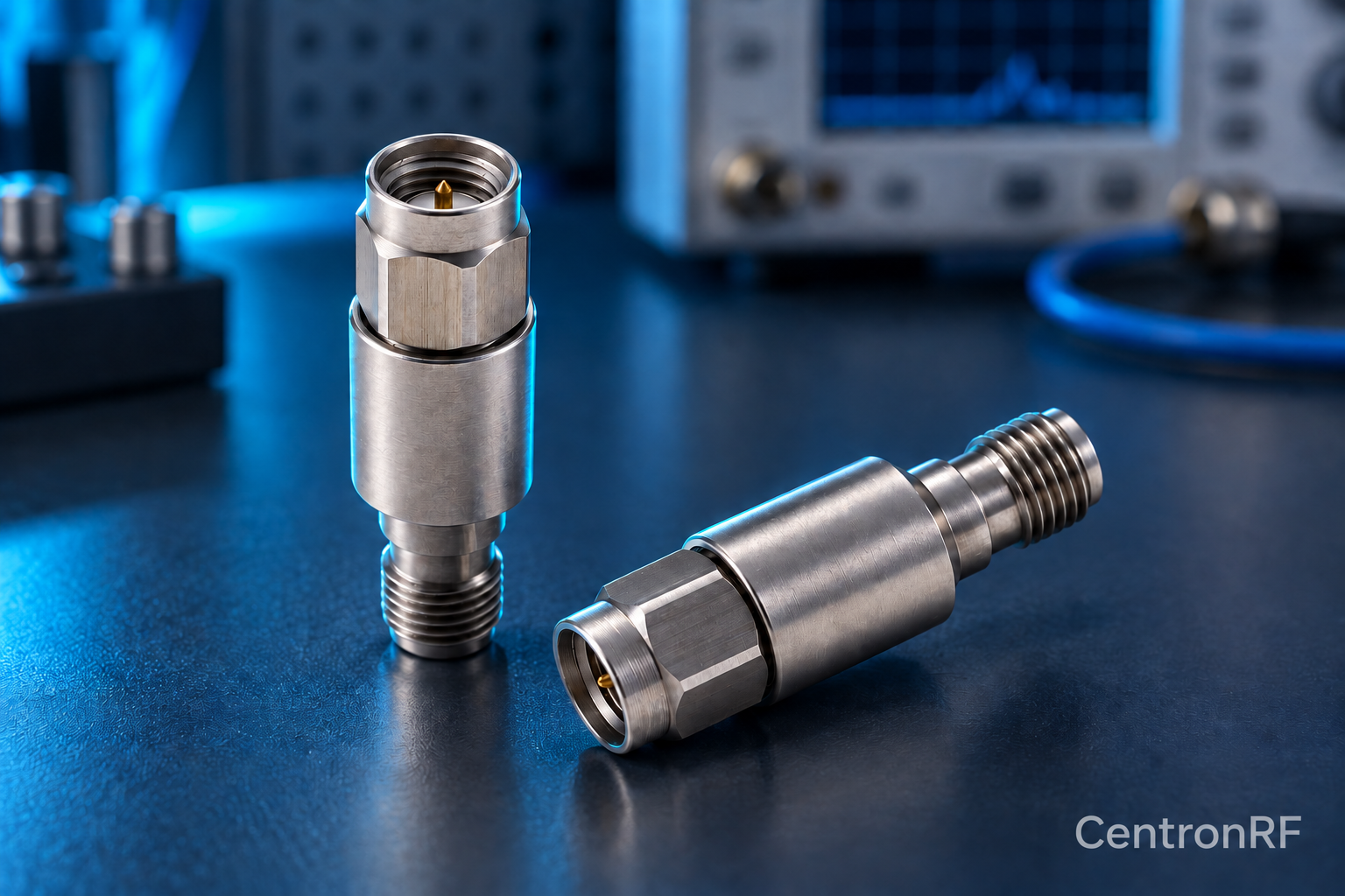
Check compatibility, mechanical condition, cable strain and calibration before changing the device under test. A bad transition can mimic a component fault.
How it works in practice
Inspect with power removed. Compare against a known-good cable or adapter within the same ratings. If the result changes after reconnecting, investigate contact condition and torque consistency. Keep reference planes consistent during comparisons. Avoid repeatedly mating a damaged part to an instrument.
Example and interpretation
An unexpected S11 change that follows an adapter swap points toward the transition rather than the tested attenuator.
Checks before use
- Inspect interfaces
- Check cable strain
- Use a controlled substitute
- Recalibrate when the path changes
Important limit
Do not force threads or contacts to overcome a suspected mismatch.
Related Centron RF product
N-type fixed attenuator for a compatible RF path. Use a product page to check both connector interfaces, nominal impedance and model-specific band and power requirements. The connector family alone cannot establish a component’s total RF capability.
Further reading
Rohde & Schwarz: Impedance, VSWR and Return Loss. This background reference explains general principles; the selected Centron RF model’s datasheet governs its own ratings.
Related guides
Educational guide. Numerical examples use the stated assumptions and are not test results for a supplied unit.