


Some divider and combiner networks use resistors to provide isolation or absorb imbalance. Resistor stress depends on the network and operating conditions.
How it works in practice
A balanced ideal state can dissipate much less power in an isolation resistor than a mismatched or failed-source state. Analyze the actual topology, phase and loads. A resistor replacement must match RF behavior and assembly requirements as well as resistance and wattage.
Example and interpretation
Loss of one input source in a combiner can change isolation-resistor stress substantially.
Checks before use
- Identify the resistor's circuit role
- Analyze imbalance states
- Check RF and thermal limits
- Verify the assembled network
Important limit
Do not size an isolation resistor from ideal balanced operation alone.
Related Centron RF product
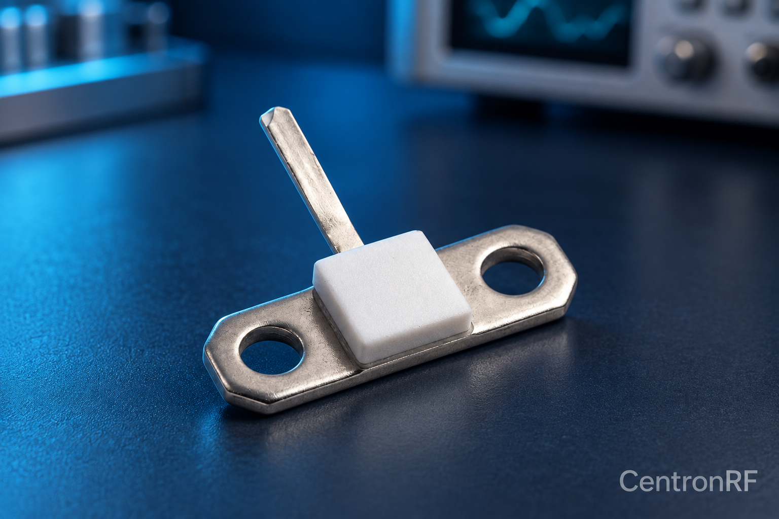
50-ohm 10 W thick-film RF resistor. The linked resistor is listed as 50 ohms, 10 W and 4 GHz. Request the recommended mounting, heatsink, derating, tolerance and pulse conditions; those determine whether it is suitable for the intended circuit.
Further reading
Vishay: Resistor Technical FAQ. This background reference explains general principles; the selected Centron RF model’s datasheet governs its own ratings.
Related guides
Educational guide. Numerical examples use the stated assumptions and are not test results for a supplied unit.