


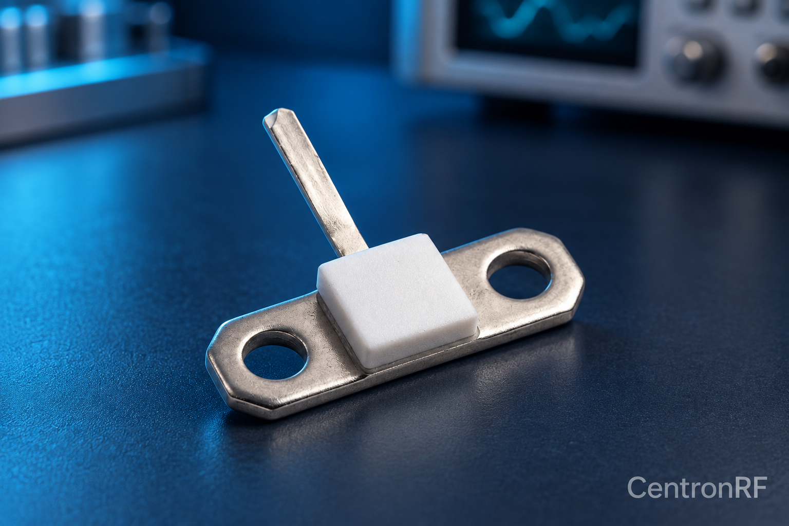
Use the manufacturer's mounting method, fastening limits and thermal interface guidance. Mechanical mounting is part of both RF and thermal performance.
How it works in practice
Keep the mounting surface suitable and avoid bending the component or stressing its leads. Follow soldering and assembly limits for the exact package. Ground and lead geometry affect high-frequency impedance. Missing assembly information should be resolved before building a production fixture.
Example and interpretation
A long connection from the resistor to ground can add inductance even when the flange is thermally well attached.
Checks before use
- Read assembly guidance
- Prepare the mounting surface
- Keep RF paths controlled
- Verify installed performance
Important limit
Do not invent a torque or soldering temperature for an unspecified component.
Related Centron RF product
50-ohm 10 W thick-film RF resistor. The linked resistor is listed as 50 ohms, 10 W and 4 GHz. Request the recommended mounting, heatsink, derating, tolerance and pulse conditions; those determine whether it is suitable for the intended circuit.
Further reading
Vishay: Resistor Technical FAQ. This background reference explains general principles; the selected Centron RF model’s datasheet governs its own ratings.
Related guides
Educational guide. Numerical examples use the stated assumptions and are not test results for a supplied unit.