


Controlled attenuation changes can help test whether measured levels follow expected dB changes. Keep the source and path stable and account for actual attenuation.
How it works in practice
Use a calibrated pad or measured step differences, not only dial labels. Watch for detector floor, overload and AGC effects. A response that stops following the expected change may indicate a range limit or setup issue. Interpret the result within the measurement uncertainty.
Example and interpretation
Adding a measured 10.1 dB loss should lower the measured level by about 10.1 dB if the system remains linear and above its floor.
Checks before use
- Stabilize the source
- Measure the attenuation change
- Check detector range
- Compare repeated results
Important limit
Agreement at one level does not establish linearity across every operating condition.
Related Centron RF product
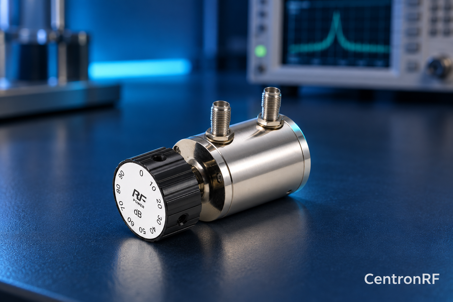
SMA rotary attenuator with 1 dB steps. The linked fine-step unit lists 0–10 dB in 1 dB increments. It can be considered for controlled level changes within its ratings. Dial resolution does not establish traceable accuracy; calibrate the assembled path as required.
Further reading
Keysight: Fundamentals of RF and Microwave Power Measurements. This background reference explains general principles; the selected Centron RF model’s datasheet governs its own ratings.
Related guides
Educational guide. Numerical examples use the stated assumptions and are not test results for a supplied unit.