


Use attenuation rated for both source power and the frequencies being measured. Correct loss separately at the fundamental and harmonics.
How it works in practice
A pad's loss can vary across the harmonic span. The analyzer must remain below overload while keeping small harmonics visible. Confirm that the source and analyzer are not generating misleading distortion in the test configuration. Include cables and couplers in frequency-specific corrections.
Example and interpretation
A 2 GHz fundamental and 6 GHz third harmonic need path characterization at both frequencies.
Checks before use
- Check source and input limits
- Rate the full frequency span
- Apply separate loss corrections
- Verify analyzer distortion behavior
Important limit
Do not apply the fundamental's attenuation correction to every harmonic without justification.
Related Centron RF product
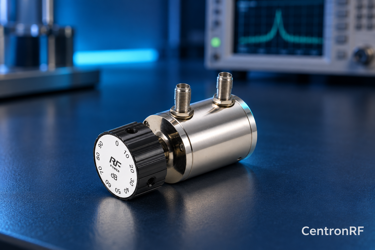
SMA rotary attenuator with 1 dB steps. The linked fine-step unit lists 0–10 dB in 1 dB increments. It can be considered for controlled level changes within its ratings. Dial resolution does not establish traceable accuracy; calibrate the assembled path as required.
Further reading
Keysight: Fundamentals of RF and Microwave Power Measurements. This background reference explains general principles; the selected Centron RF model’s datasheet governs its own ratings.
Related guides
Educational guide. Numerical examples use the stated assumptions and are not test results for a supplied unit.