


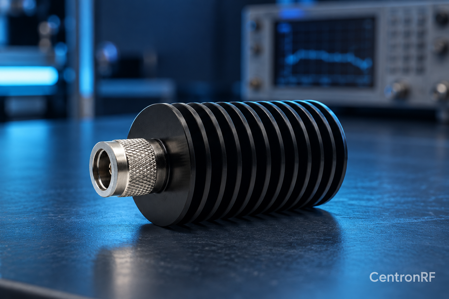
In a matched ideal resistive pad, dissipated power is input power minus output power. Use the output ratio implied by attenuation.
How it works in practice
The result estimates heat generation under the stated conditions. Reflected power, connector losses and real construction can change the detailed distribution. Compare with the manufacturer's input rating and cooling conditions rather than treating the arithmetic as a thermal qualification.
Example and interpretation
With 5 W input and 10 dB attenuation, output is 0.5 W and approximately 4.5 W is dissipated.
Checks before use
- Calculate output power
- Subtract from input
- Check thermal conditions
- Include peak and mismatch requirements
Important limit
Do not assume a nominal wattage rating equals an unrestricted heat-removal capacity.
Related Centron RF product
SMA 2 W 6 GHz fixed attenuator. Use calculated levels to define a requirement, then compare it with the exact product’s current bandwidth, input power, impedance and available attenuation options. Calculations assume stated conditions and do not replace a component datasheet.
Further reading
Keysight: Fundamentals of RF and Microwave Power Measurements. This background reference explains general principles; the selected Centron RF model’s datasheet governs its own ratings.
Related guides
Educational guide. Numerical examples use the stated assumptions and are not test results for a supplied unit.