


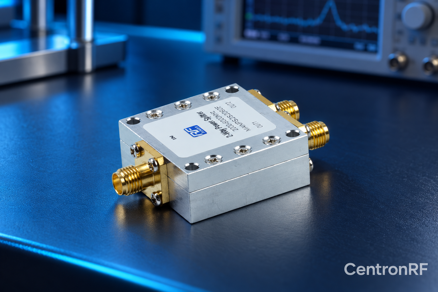
An RF power divider distributes an input signal among multiple outputs according to its design. Equal dividers nominally deliver equal branch powers when the ports are properly matched.
How it works in practice
Divider topology determines bandwidth, isolation, impedance behavior and combining suitability. Insertion loss includes unavoidable division loss plus excess loss. Check the defined port arrangement and terminate branches as required. Product photos cannot reveal every internal characteristic.
Example and interpretation
An ideal equal two-way divider sends half the input power to each branch, approximately 3.01 dB below the input.
Checks before use
- Check port count
- Check impedance and band
- Check loss and isolation
- Terminate branches correctly
Important limit
Do not interpret ideal division loss as a manufacturing defect.
Related Centron RF product
RF power divider range. Compare the exact divider model, port count and current datasheet. Some catalog titles show inconsistent frequency ranges, so confirm the supplied model’s full passband, loss, isolation and power limits before selection.
Further reading
Mini-Circuits: Understanding Power Splitters. This background reference explains general principles; the selected Centron RF model’s datasheet governs its own ratings.
Related guides
Educational guide. Numerical examples use the stated assumptions and are not test results for a supplied unit.