


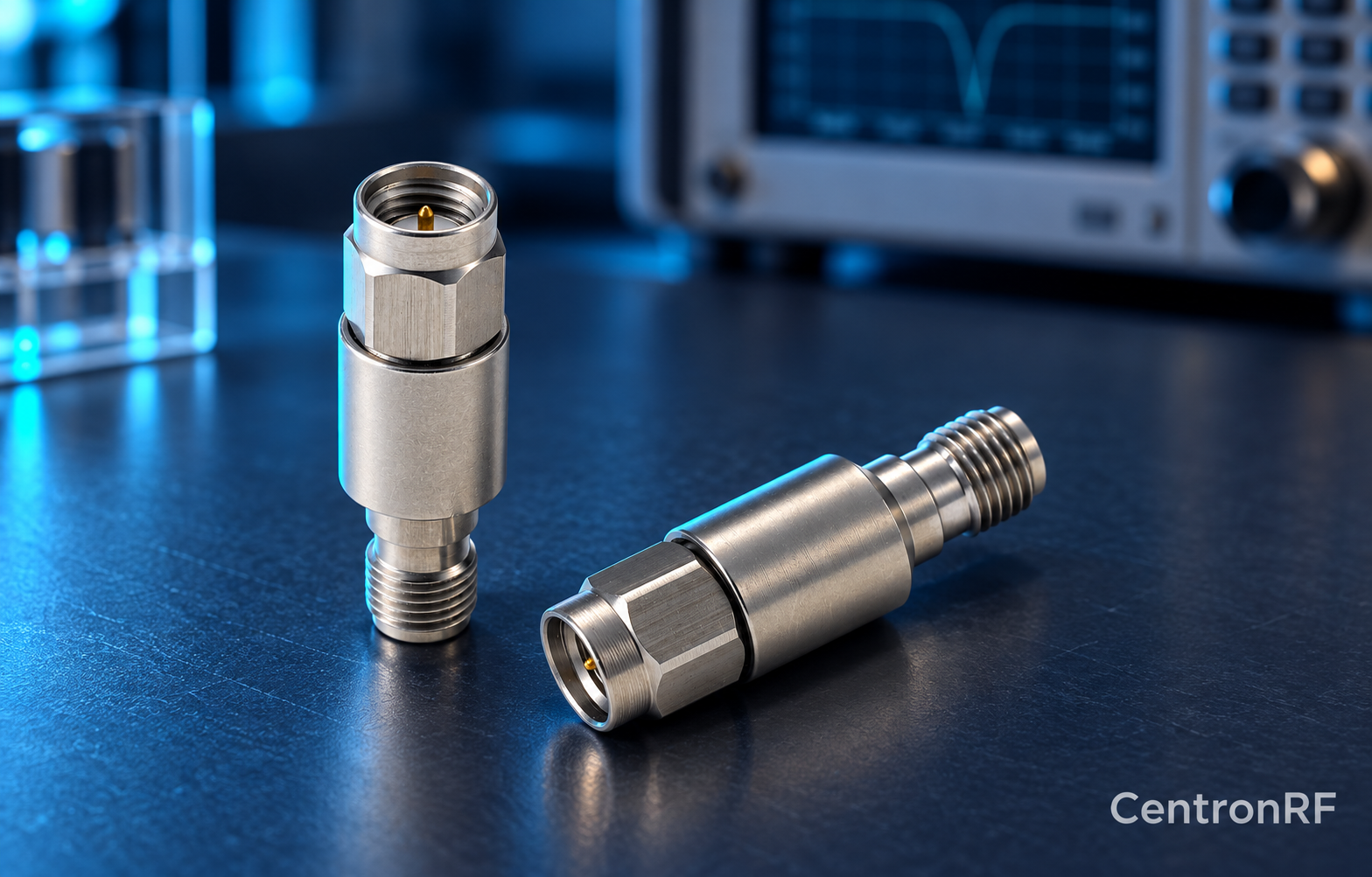
Include the DC block's measured insertion loss in the complete RF path budget. Loss may vary with frequency and can matter near its lower band edge.
How it works in practice
Measure the installed component with appropriate calibration planes or use verified data for the exact model. Account for its connectors and any required adapters. When reporting received power, specify whether the block is inside or outside the calibrated reference plane.
Example and interpretation
If a block adds 0.4 dB at the operating frequency, a nominal −10 dBm upstream signal becomes about −10.4 dBm downstream before other losses.
Checks before use
- Define the reference plane
- Obtain frequency-specific loss
- Include adapters
- Apply the path correction
Important limit
Do not assume a DC block is transparent to RF.
Related Centron RF product
SMA DC block listed for 8 GHz applications. The linked SMA block gives an upper-frequency reference. Confirm its lower passband limit, working voltage, RF power and whether it blocks the inner, outer or both conductors. A catalog range starting with DC should not be interpreted as DC transmission.
Further reading
Mini-Circuits: DC Block Specifications. This background reference explains general principles; the selected Centron RF model’s datasheet governs its own ratings.
Related guides
- Checking DC Isolation Without Misreading the Result
- Where to Place a DC Block in a Measurement Chain
Educational guide. Numerical examples use the stated assumptions and are not test results for a supplied unit.