


A DC block interrupts a DC path; a bias tee combines or separates DC and RF through dedicated ports. Select the function your signal path needs.
How it works in practice
A bias tee typically has RF, DC and combined ports, with specific current, voltage and frequency limits. Its RF-only port may already contain a blocking element, but verify the diagram. Adding an external block in the combined path can prevent intended bias from reaching the powered device.
Example and interpretation
A remote RF amplifier can receive bias through a bias tee, while a block on the instrument-facing path prevents that bias from reaching a sensitive input.
Checks before use
- Draw RF and DC paths
- Identify each bias-tee port
- Check intended DC continuity
- Rate all components
Important limit
Do not install a block where it unintentionally removes required device power.
Related Centron RF product
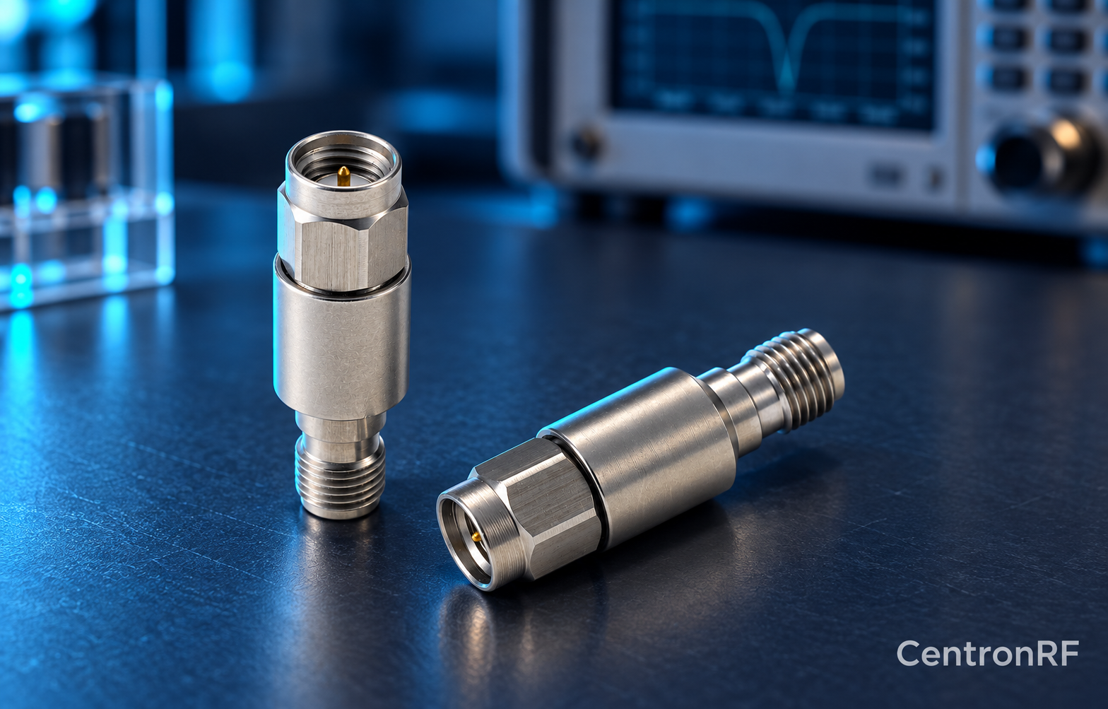
SMA DC block listed for 8 GHz applications. The linked SMA block gives an upper-frequency reference. Confirm its lower passband limit, working voltage, RF power and whether it blocks the inner, outer or both conductors. A catalog range starting with DC should not be interpreted as DC transmission.
Further reading
Mini-Circuits: DC Block Specifications. This background reference explains general principles; the selected Centron RF model’s datasheet governs its own ratings.
Related guides
Educational guide. Numerical examples use the stated assumptions and are not test results for a supplied unit.