


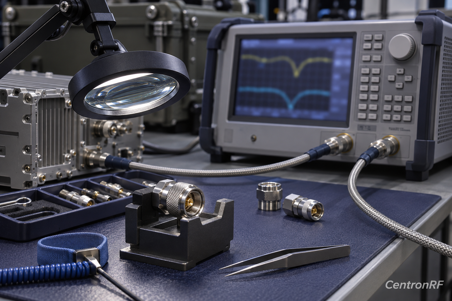
SMA and 2.92 mm connectors can be mechanically compatible, but mating them does not make an RF test path suitable for the higher connector’s frequency rating. For aerospace and defense electronics test benches, the useful question is whether the complete cable, adapter and instrument interface remains repeatable over the required band, handling cycle and operating environment.
A connector that fits can still introduce mismatch, move the measurement reference plane or damage an expensive precision port. This guide explains how to specify mixed connector paths for equipment maintenance, qualification support and laboratory measurements without treating a connector name as proof of system performance.
Why connector compatibility matters in defense electronics testing
A maintenance bench may connect a modern instrument to a legacy coaxial interface through several generations of adapters. Different technicians may assemble that path on different shifts. If the procedure only says “use an SMA cable,” two apparently valid setups can have different loss, phase delay and mechanical loading.
The practical requirement is configuration control: identify the actual interfaces, select an appropriate transition, measure the installed route and preserve the conditions under which that result is valid. This applies to ordinary communications and electronics test equipment; an application label alone does not establish environmental qualification, procurement approval or compliance with a particular standard.
Mechanical mating and electrical bandwidth are different checks
Keysight identifies SMA, 3.5 mm and 2.92 mm as an intermateable connector group, while also describing precautions when mating SMA male connectors to precision interfaces. Its connector guidance gives 40 GHz as the operating ceiling for the specified 2.92 mm interface. Those statements do not extend the rating of an arbitrary SMA cable or adapter. See Keysight’s coaxial connector overview.
| Interface question | Engineering check |
|---|---|
| Will the connectors mate? | Confirm family, gender, center-contact geometry and manufacturer instructions. |
| Will the route perform over the test band? | Check every assembly’s rated bandwidth and measured loss and match. |
| Can the interface tolerate repeated use? | Inspect wear, apply specified coupling torque and control cable loading. |
| Does the part meet the application requirement? | Obtain documentation for the exact part and configuration, rather than relying on its connector family. |
In particular, 1.85 mm and 2.4 mm belong to a different mating group. Similar appearance is not a reason to try an uncertain connection. The component drawing and instrument manual should resolve ambiguity before physical contact.
Inspect the connector before protecting the measurement
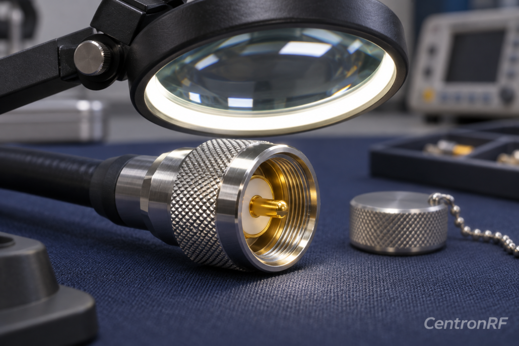
Inspect both sides of the intended connection, not just the inexpensive cable end. Look for contamination, damaged threads, abnormal center contacts and worn mating surfaces. Where the interface and procedure require dimensional checks, use the appropriate connector gauge and its instructions. Visual inspection alone cannot certify pin depth or dimensional conformity.
Keep precision interfaces protected when they are not in use. Align the pair without side loading, hold the bodies as specified and tighten the coupling nut using the torque value for the actual connection. Avoid borrowing a torque value from a different family or applying extra force to correct an uncertain fit. Keysight’s connector-care guidance is a useful starting point; the relevant equipment manual remains the procedure reference.
A replaceable port saver can be a sensible maintenance choice, but it becomes part of the electrical path. Record its identity and characterize it with the cable route. Replacing a worn saver without checking the route can trade a mechanical improvement for an unrecorded measurement change.
Where should the reference plane be?
The reference plane is the point to which the measurement result applies. A calibration at the instrument port does not automatically remove a later cable, adapter or protective component. If the intended result describes the equipment connector, the measurement plan must account for everything between that connector and the calibrated instrument interface.
For network measurements, select a calibration or characterized-fixture approach compatible with the actual interfaces. A simple delay correction is not a universal substitute for correcting mismatch and transmission loss. For power measurements, determine the loss at the relevant frequencies and levels and account for mismatch and instrument uncertainty. Keysight’s calibration guidance explains the distinction between a calibrated reference plane and the intervening fixture.
As a planning example, a route with 1.2 dB cable loss, 0.3 dB adapter loss and 0.2 dB additional passive loss has 1.7 dB nominal transmission loss. That arithmetic is an initial budget, not a measured calibration result. The assembled route may have frequency-dependent interaction that is not captured by adding three catalog numbers.
Include attenuators, DC blocks and loads in the same interface record
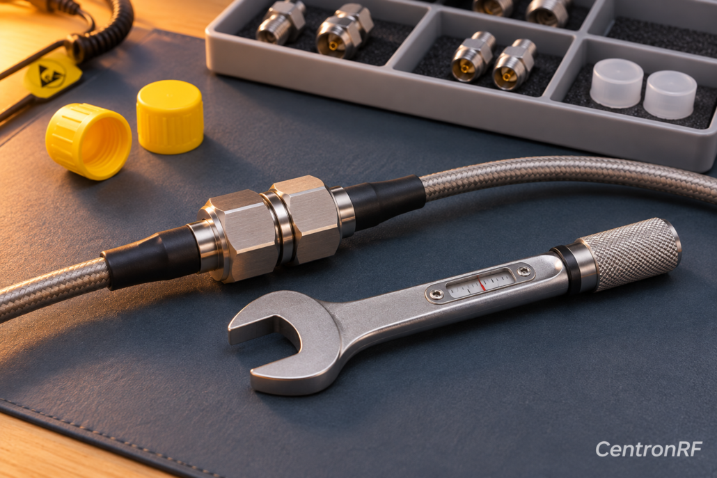
An attenuator used to set a test level also contributes connector transitions, frequency response and phase. A DC block may be needed at a biased interface, but its operating band and DC rating must suit that location. A termination used for verification needs a suitable match and power rating. Each accessory should therefore be identified by part and position, not simply listed as “RF hardware.”
A useful record includes a route drawing, connector types at both ends, cable and adapter identifiers, test band, power and bias limits, calibration method and verification results. Where a change is allowed without repeating calibration, state the evidence and acceptance criterion supporting that exception.
For related selection context, the RF attenuator category illustrates why bandwidth, connector and power specifications need to be considered together. A product listing supports initial selection; qualification still depends on the exact delivered part and the application’s evidence requirements.
A practical release check for a shared bench
- Confirm that the drawing matches the installed cable and adapter route.
- Inspect and, where required, gauge the mating interfaces.
- Apply the documented assembly and torque procedure.
- Verify the reference plane and correction data for the configured route.
- Measure a suitable verification device before accepting equipment results.
- Record what changes require re-verification, including cable movement and port-saver replacement.
Acceptance limits should come from the measurement requirement and uncertainty budget. A connector that passes a casual continuity check has not necessarily passed a microwave match or repeatability requirement.
Common questions
Does a 2.92 mm adapter upgrade an SMA cable to 40 GHz?
No. The complete route remains limited by its individual component specifications and verified assembled performance.
Is mechanical compatibility enough for an aerospace or defense application?
No. It does not establish electrical performance, environmental qualification, traceability or procurement authorization.
Should an adapter change trigger a new check?
Yes, unless the measurement procedure explicitly permits that substitution and has evidence showing the result remains within its acceptance limits.
Related reading: specifying connector interfaces for a portable aerospace RF test kit.
Leave a Reply