


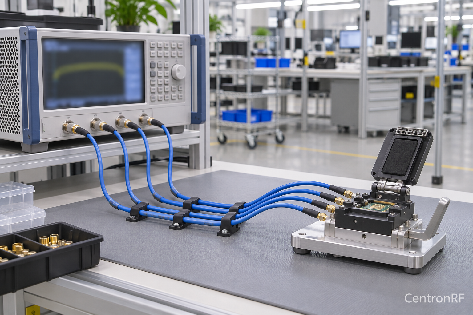
A phase-stable RF cable keeps its transmission phase sufficiently consistent under the movement, temperature and handling conditions of a test. In manufacturing, that stability matters because a production fixture should distinguish changes in the device under test from changes in the measurement route.
Equal cable length is not the same as equal electrical delay, and low insertion loss is not a guarantee of stable phase. This guide explains how manufacturing teams can specify, verify and maintain coaxial test paths when phase repeatability affects a production decision.
Why small delay changes become large phase changes
For a simple transmission path, phase depends on frequency and propagation delay. The magnitude of the phase change caused by a delay change is:
|Δφ| = 360 × f × |Δτ|, with phase in degrees, frequency in hertz and delay in seconds.
At 10 GHz, a 1 ps delay change corresponds to 3.6°. At 28 GHz, the same delay change corresponds to 10.08°. These are calculated examples, not measurements of a particular cable. They explain why a route that is adequate for an amplitude-only check can become problematic in a phase-sensitive measurement.
For a reasonably uniform coaxial line, delay depends on both physical length and propagation velocity. Cable construction, dielectric behavior and the assembled connector transitions all matter. Cutting two different cable types to the same physical length does not establish equal electrical length.
Separate phase matching from phase stability
| Requirement | What it asks | What it does not establish |
|---|---|---|
| Phase matching | How closely two paths agree under specified conditions | That their relationship stays unchanged after movement or temperature change |
| Phase stability | How much a path changes under a defined disturbance | That it initially matches another cable |
| Amplitude stability | How consistently transmission magnitude is maintained | That phase remains within the required limit |
Write each requirement with a frequency range, disturbance and acceptance criterion. “Phase stable” without a bend condition, temperature condition or measurement method is difficult to use as an incoming-inspection requirement.
Flexure should represent the actual fixture movement
A cable may move when an operator opens a fixture, inserts a module or reaches a connector. The important movement is therefore the one that occurs in production, not an arbitrary bend performed on a loose cable. Support the assembly so that the connector does not carry the weight or twisting force of the route.
Respect the manufacturer’s minimum bend radius, but recognize that avoiding mechanical damage is only one objective. A route near that limit can still be less stable than one with generous bends. Avoid changing the bend plane, loop position and clamping arrangement between calibration and use.
Gore’s discussion of loss and phase changes identifies flexure and environmental conditions as important assembly considerations. Product-specific stability claims should always be interpreted with their test conditions rather than transferred to a different cable construction.
Temperature is part of the measurement condition
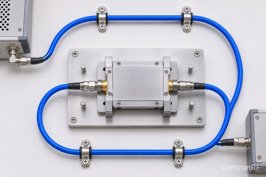
Temperature changes the physical and electrical behavior of a cable route. In a factory, the cause may be an environmental test, an instrument exhaust, a warm device or simply handling the cable. The cable and fixture may also take different amounts of time to reach a stable condition.
Define the temperature range and stabilization rule used for the production decision. For a chamber measurement, distinguish the part of the cable inside the chamber from the section outside it. Record feedthroughs and transitions as part of the route. A chamber setpoint is not evidence that every component in the test path has reached that temperature.
Do not assume phase drift is a single linear coefficient across a wide range unless the assembly data or measurement supports that model. Review the cable’s environmental specifications and determine which changes are reversible, which require re-verification and which indicate damage.
Build a useful fixture verification sequence
Start with a stable measurement configuration and a suitable reference connection. Establish baseline transmission magnitude and unwrapped phase over the required sweep. If comparing two paths, define whether the decision concerns each absolute phase or their relative phase difference. An unchanged common delay and a changed path imbalance have different implications.
- Install the cables in their normal production routing and allow the setup to stabilize.
- Perform the required calibration and save a baseline verification sweep.
- Exercise the fixture through its intended opening, loading and unloading movement.
- Repeat the measurement without silently recalibrating away the movement effect.
- Compare changes over the whole band and repeat enough cycles to evaluate consistency.
- Document conditions, raw data, corrections and the acceptance rule.
A single phase reading can hide phase wrapping or a frequency-specific problem. Use appropriate unwrapping and, where relevant, examine group delay. Choose limits from the product test requirement and measurement uncertainty; a convenient round number is not automatically a defensible production limit.
Account for passive accessories and calibration changes
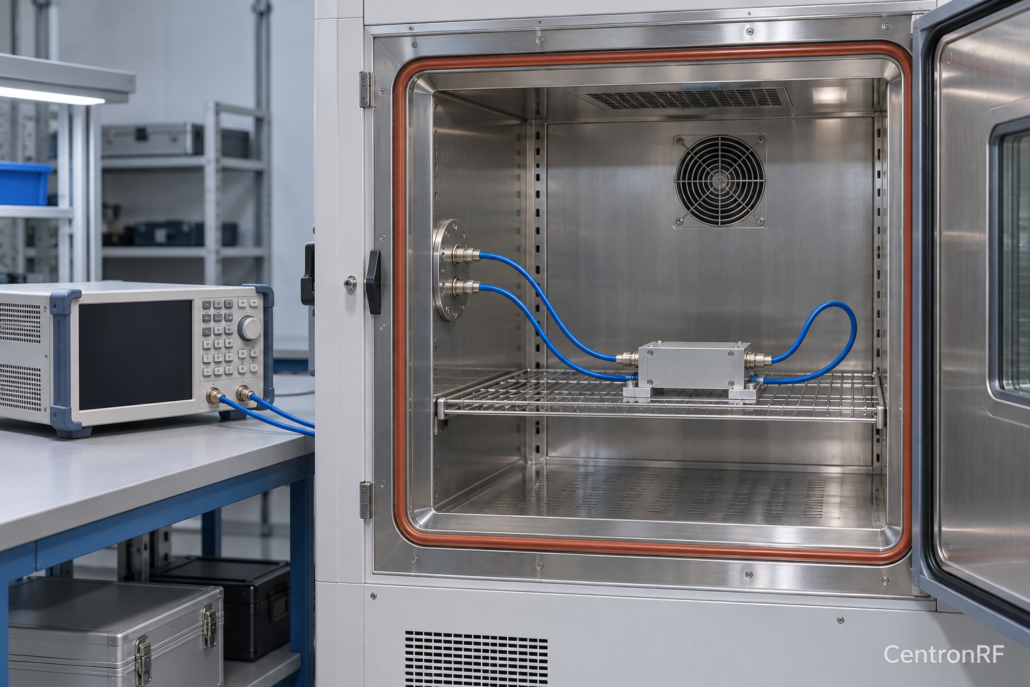
Production routes often contain an attenuator, adapter, DC block or splitter in addition to the cables. Replacing a cable with an equivalent length does not preserve the phase response of those other items. Likewise, changing an attenuation setting can change both magnitude and phase, depending on the component.
Where a fixed or rotary RF attenuator is part of the fixture, characterize the settings actually used. If bias isolation requires a DC block, check its response throughout the operating band. Neither equal attenuation values nor equal connector names prove equal phase.
Calibration can remove systematic errors for a configured route, but it cannot make a moving or damaged route inherently stable. Keysight’s calibration guidance discusses the role of cables, fixtures and adapters between an instrument and its reference plane. Preserve the calibrated arrangement, or re-establish the evidence when it changes.
Use evidence to decide when to replace a cable
Record cable identity, service history and the fixture position. Track trends in loss, match and phase variation rather than waiting for a completely open connection. A cable that remains electrically continuous can still create an unstable production measurement.
Set a response for each failure mode: re-route a disturbed assembly, inspect a connector after an abnormal load, re-verify a replacement, or remove a cable that no longer meets the documented limits. Keep a known suitable spare route so that troubleshooting does not become a series of uncontrolled substitutions.
Common questions
Are equal-length cables automatically phase matched?
No. Electrical delay depends on construction, propagation velocity, connectors and the assembled route as well as length.
Can recalibration replace a cable stability check?
No. Recalibration can correct a stable configuration. A stability check determines how that configuration changes during its intended use.
Should a phase-sensitive fixture have a different maintenance rule?
Its verification should include the phase behavior that affects the production decision, alongside the appropriate loss, match and mechanical checks.
Related reading: RF cable delay and electrical length.
Leave a Reply