


Measure reflection with a calibrated method at the intended connector plane. Return loss indicates matching under the defined reference impedance.
How it works in practice
Use an appropriate calibration standard set and protect the instrument from external power or DC. Cables and adapters outside the calibrated plane contribute error. Very good matches can approach the setup's directivity limit, so uncertainty matters. Report frequency and the measurement configuration.
Example and interpretation
A displayed 35 dB return loss may require careful verification if the setup's residual reflection error is comparable to the measured signal.
Checks before use
- Isolate external sources
- Calibrate at the interface
- Check directivity limits
- Report uncertainty
Important limit
Do not claim extreme matching accuracy from an unverified fixture.
Related Centron RF product
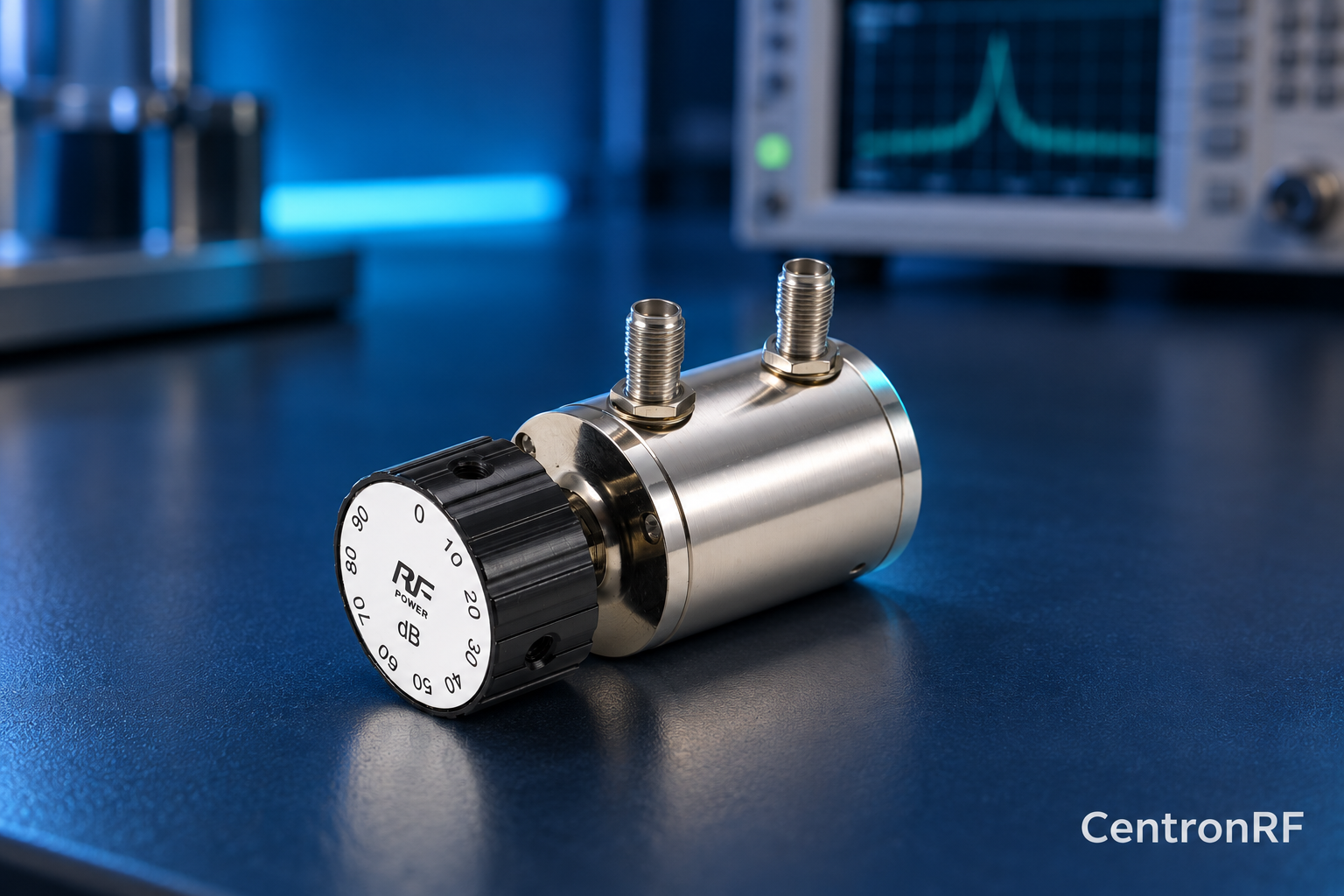
SMA rotary attenuator with 1 dB steps. The linked fine-step unit lists 0–10 dB in 1 dB increments. It can be considered for controlled level changes within its ratings. Dial resolution does not establish traceable accuracy; calibrate the assembled path as required.
Further reading
Keysight: Fundamentals of RF and Microwave Power Measurements. This background reference explains general principles; the selected Centron RF model’s datasheet governs its own ratings.
Related guides
- RF Harmonic Measurements with an External Attenuator
- Measuring High Attenuation Near the Instrument Floor
Educational guide. Numerical examples use the stated assumptions and are not test results for a supplied unit.