


Keep the analyzer input within its specified RF, DC and transient limits using a properly rated measurement path. Start from the worst-case source output.
How it works in practice
An external attenuator or coupler can lower RF level, but each has its own power and frequency limits. Internal analyzer attenuation does not necessarily protect every vulnerable input stage. Check the analyzer manual, including maximum safe input versus overload behavior. Remove unintended DC with suitable protection.
Example and interpretation
A 30 dBm source reduced by 30 dB reaches approximately 0 dBm before other losses, assuming a matched path.
Checks before use
- Read input damage limits
- Budget worst-case level
- Rate external protection
- Begin with conservative settings
Important limit
A low displayed reading does not prove the input hardware was never overloaded.
Related Centron RF product
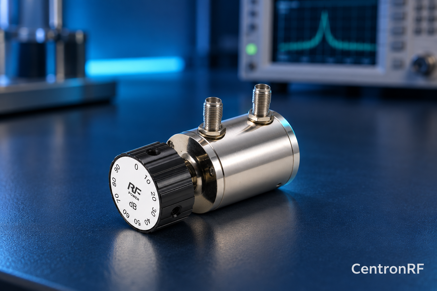
SMA rotary attenuator with 1 dB steps. The linked fine-step unit lists 0–10 dB in 1 dB increments. It can be considered for controlled level changes within its ratings. Dial resolution does not establish traceable accuracy; calibrate the assembled path as required.
Further reading
Keysight: Fundamentals of RF and Microwave Power Measurements. This background reference explains general principles; the selected Centron RF model’s datasheet governs its own ratings.
Related guides
Educational guide. Numerical examples use the stated assumptions and are not test results for a supplied unit.