


Measure transmission through the attenuator relative to a defined reference path, using an instrument range appropriate for the expected loss.
How it works in practice
Use a calibrated VNA or a suitable source and power-measurement method. Rate the measuring inputs safely. Include mismatch and instrument uncertainty when reporting accuracy. High-loss measurements need sufficient dynamic range and shielding. Record frequency and the exact selected attenuation state.
Example and interpretation
A measured S21 magnitude of −20.3 dB indicates 20.3 dB insertion loss under the measurement conditions.
Checks before use
- Define reference planes
- Calibrate the method
- Check instrument range
- Report loss with conditions
Important limit
A nominal 20 dB marking is not an individual measured value.
Related Centron RF product
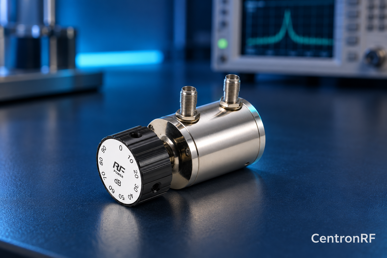
SMA rotary attenuator with 1 dB steps. The linked fine-step unit lists 0–10 dB in 1 dB increments. It can be considered for controlled level changes within its ratings. Dial resolution does not establish traceable accuracy; calibrate the assembled path as required.
Further reading
Keysight: Fundamentals of RF and Microwave Power Measurements. This background reference explains general principles; the selected Centron RF model’s datasheet governs its own ratings.
Related guides
- Using an Attenuator to Check Measurement Linearity
- RF Harmonic Measurements with an External Attenuator
Educational guide. Numerical examples use the stated assumptions and are not test results for a supplied unit.