


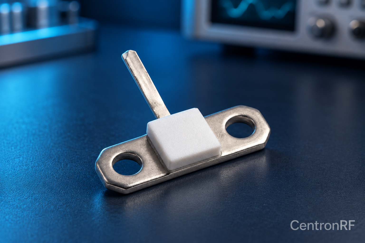
Keep the transmission-line transition and return path controlled according to the component's recommended RF layout. Nominal resistance alone does not create a matched path.
How it works in practice
Trace geometry, substrate, lead connections and grounding determine the installed impedance. Avoid broad claims about a layout without measurement or appropriate analysis. Use the intended connector transition and calibration plane when evaluating the finished path.
Example and interpretation
A short, controlled connection may outperform a long wire to the same 50-ohm resistor at GHz frequencies.
Checks before use
- Use the recommended footprint
- Control line impedance
- Provide a defined return path
- Measure installed RF behavior
Important limit
Do not assume any PCB trace connected to 50 ohms is itself a 50-ohm line.
Related Centron RF product
50-ohm 10 W thick-film RF resistor. The linked resistor is listed as 50 ohms, 10 W and 4 GHz. Request the recommended mounting, heatsink, derating, tolerance and pulse conditions; those determine whether it is suitable for the intended circuit.
Further reading
Vishay: Resistor Technical FAQ. This background reference explains general principles; the selected Centron RF model’s datasheet governs its own ratings.
Related guides
Educational guide. Numerical examples use the stated assumptions and are not test results for a supplied unit.