


Resistance tolerance contributes to impedance error, but high-frequency parasitics and mounting also affect the finished termination's match.
How it works in practice
Use the specified resistance tolerance for initial selection and verify RF impedance in the assembled circuit. Connector geometry, grounding and trace transitions can dominate at high frequency. Low DC tolerance does not automatically produce low VSWR over a wide band.
Example and interpretation
A resistor within 1% of 50 ohms can still show a poor GHz match when connected through a long inductive lead.
Checks before use
- Check tolerance
- Minimize uncontrolled transitions
- Measure installed S11
- Compare over the band
Important limit
Do not use resistance tolerance as a complete RF matching specification.
Related Centron RF product
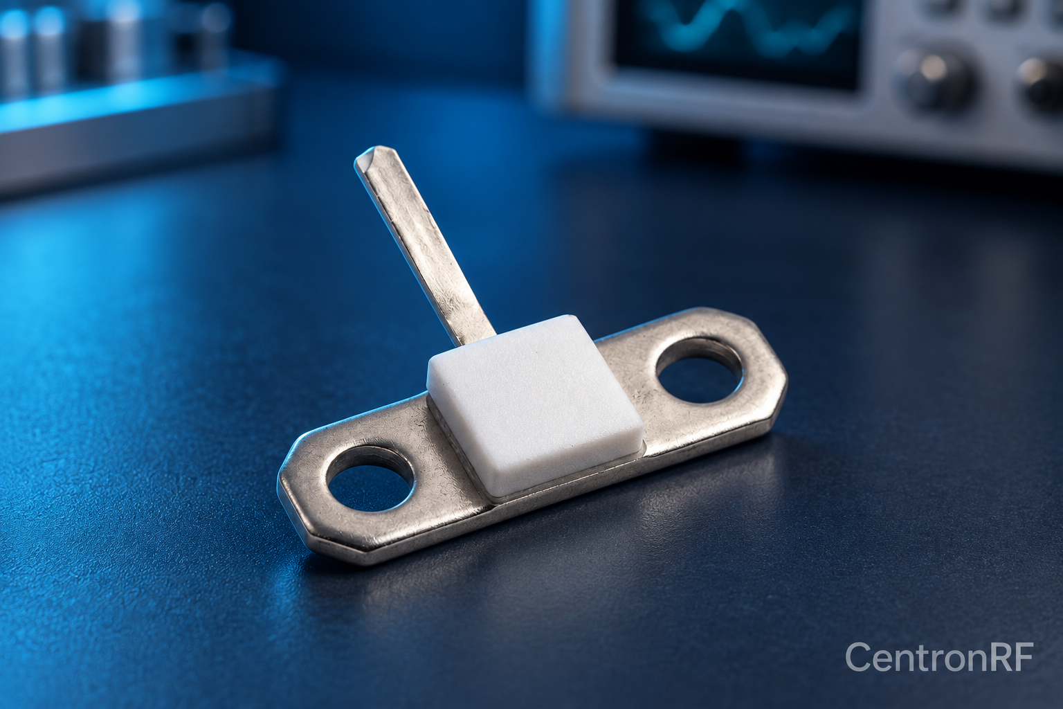
50-ohm 10 W thick-film RF resistor. The linked resistor is listed as 50 ohms, 10 W and 4 GHz. Request the recommended mounting, heatsink, derating, tolerance and pulse conditions; those determine whether it is suitable for the intended circuit.
Further reading
Vishay: Resistor Technical FAQ. This background reference explains general principles; the selected Centron RF model’s datasheet governs its own ratings.
Related guides
- Thermal Resistance and RF Resistor Temperature Rise
- RF Resistor Failure Analysis: Start with the Circuit
Educational guide. Numerical examples use the stated assumptions and are not test results for a supplied unit.