


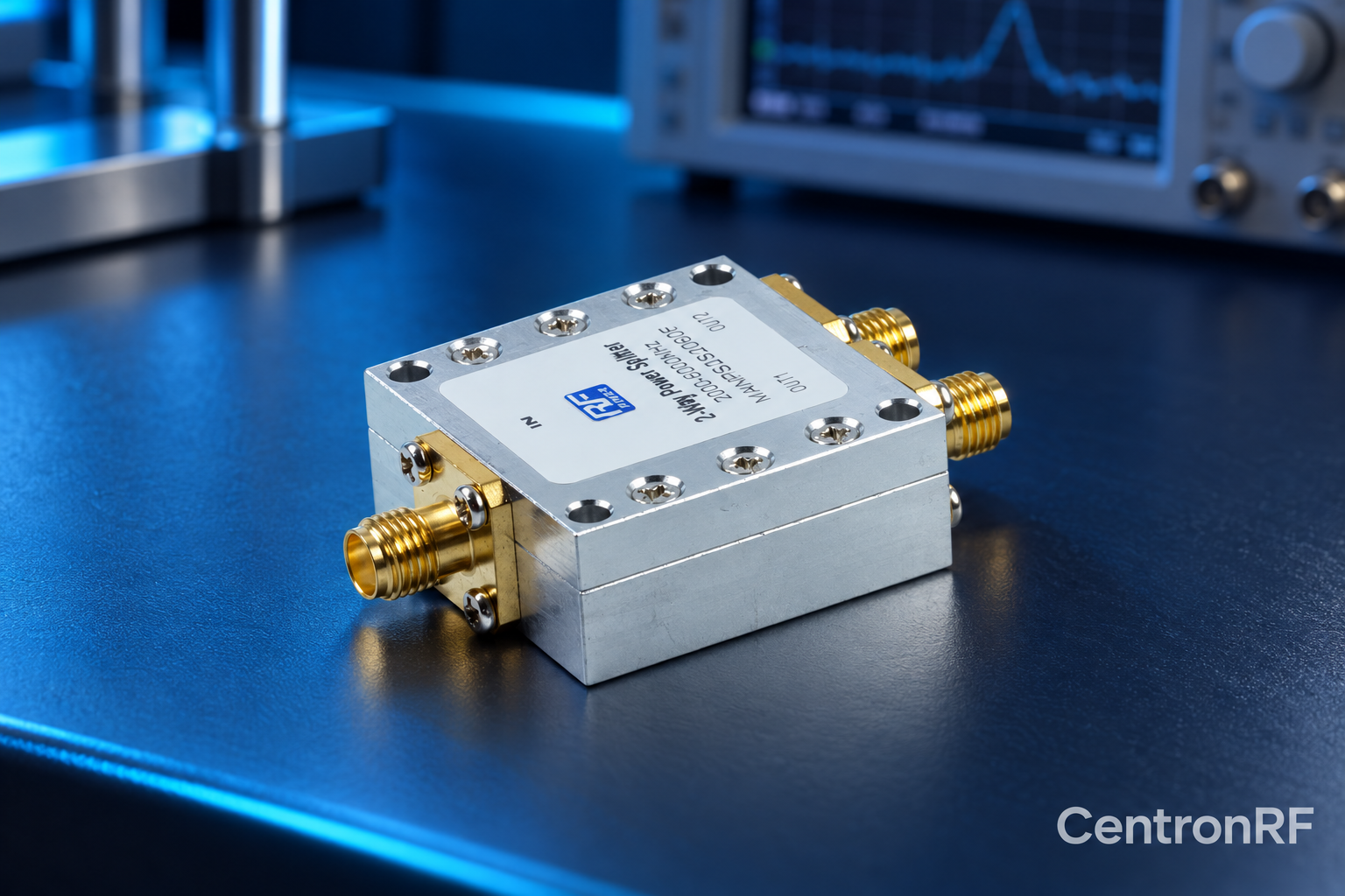
A divider distributes substantial signal power among outputs; a directional coupler samples a defined fraction and separates propagation directions according to its design.
How it works in practice
Use a coupler when a small measurement sample or forward/reflected distinction is required. Use a divider for signal distribution when division loss is acceptable. Coupler coupling, directivity and through loss are different parameters from divider balance and output isolation.
Example and interpretation
A 20 dB coupler ideally samples about 1% of through-path power, unlike an equal two-way divider's 50% branch share.
Checks before use
- Define sampling or distribution
- Check required level
- Check directional requirements
- Rate all ports
Important limit
Do not substitute a divider when directional discrimination is required.
Related Centron RF product
RF power divider range. Compare the exact divider model, port count and current datasheet. Some catalog titles show inconsistent frequency ranges, so confirm the supplied model’s full passband, loss, isolation and power limits before selection.
Further reading
Mini-Circuits: Understanding Power Splitters. This background reference explains general principles; the selected Centron RF model’s datasheet governs its own ratings.
Related guides
Educational guide. Numerical examples use the stated assumptions and are not test results for a supplied unit.