


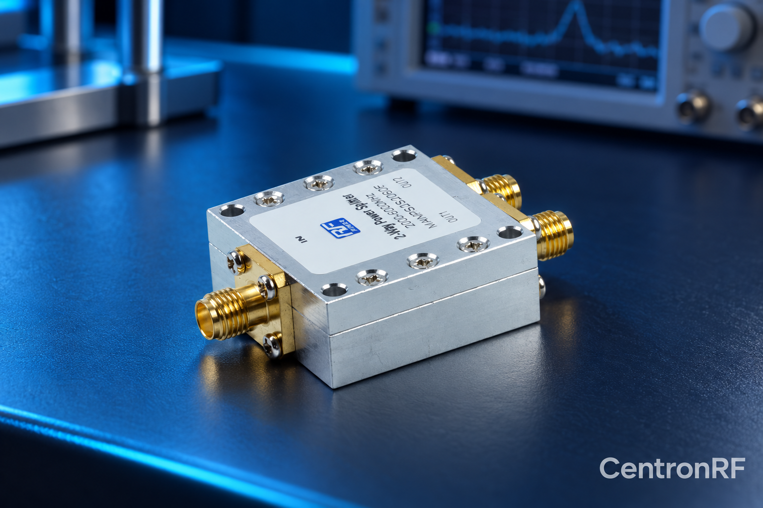
Resistive and Wilkinson dividers use different networks, leading to different loss, bandwidth and isolation behavior. Choose from specifications for the actual design.
How it works in practice
A resistive network can support broad low-frequency operation but dissipates signal power. A Wilkinson design uses transmission-line behavior and isolation resistance, with frequency-dependent performance. Practical implementations vary, so topology names do not replace measured data.
Example and interpretation
A DC-capable resistive divider and a band-limited Wilkinson unit may solve different test-distribution problems.
Checks before use
- Define low-end bandwidth
- Compare total loss
- Compare isolation
- Check power and combining limits
Important limit
Do not assign ideal textbook performance to an unspecified commercial device.
Related Centron RF product
RF power divider range. Compare the exact divider model, port count and current datasheet. Some catalog titles show inconsistent frequency ranges, so confirm the supplied model’s full passband, loss, isolation and power limits before selection.
Further reading
Mini-Circuits: Understanding Power Splitters. This background reference explains general principles; the selected Centron RF model’s datasheet governs its own ratings.
Related guides
- Power Splitter Troubleshooting: Unequal Output Levels
- Specifying a Divider for an Antenna Feed Network
Educational guide. Numerical examples use the stated assumptions and are not test results for a supplied unit.