


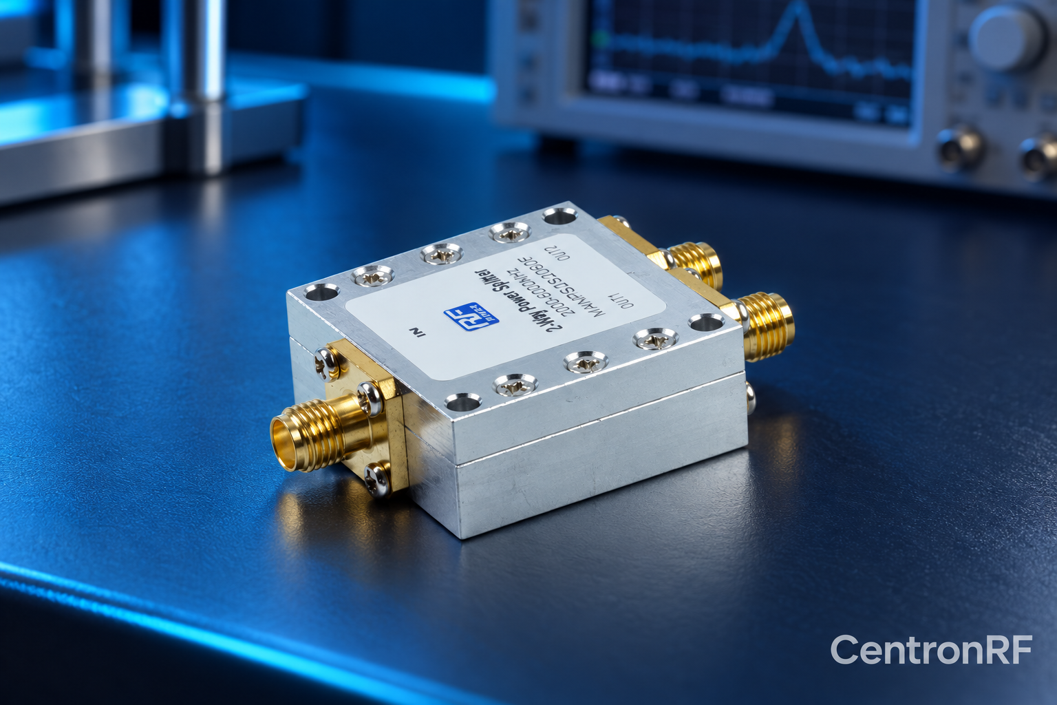
Terminations may absorb imbalance or unwanted power in a combining network. Their location and rating depend on the divider or combiner topology.
How it works in practice
Study the manufacturer's combining diagram and limits. Unequal amplitudes, phase error or a failed source can change where power goes. Some networks contain internal isolation resistors; others require external loads. Check the worst permitted operating state rather than only ideal equal inputs.
Example and interpretation
If one source shuts down, the remaining source may stress an isolation element differently from balanced operation.
Checks before use
- Identify all dissipation paths
- Check failed-source conditions
- Rate terminations
- Follow the documented configuration
Important limit
Do not assume an internal resistor can absorb unlimited imbalance.
Related Centron RF product
RF power divider range. Compare the exact divider model, port count and current datasheet. Some catalog titles show inconsistent frequency ranges, so confirm the supplied model’s full passband, loss, isolation and power limits before selection.
Further reading
Mini-Circuits: Understanding Power Splitters. This background reference explains general principles; the selected Centron RF model’s datasheet governs its own ratings.
Related guides
Educational guide. Numerical examples use the stated assumptions and are not test results for a supplied unit.