


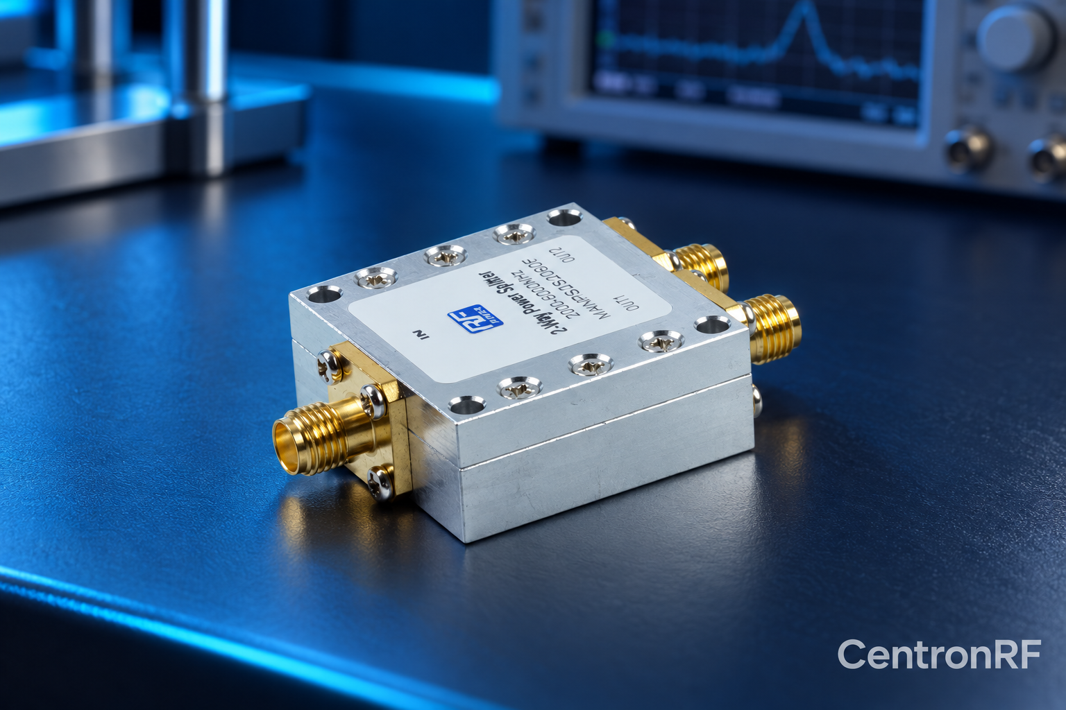
Amplitude balance is the difference between output levels of a divider. It is distinct from each branch's total insertion loss.
How it works in practice
Measure branches under the same input and termination conditions. Use identical measurement configurations or apply calibrated corrections so cable and sensor differences do not appear as divider imbalance. Compare against the model's stated limit, not an assumed universal value.
Example and interpretation
Branch losses of 3.4 dB and 3.7 dB imply 0.3 dB amplitude imbalance in that measurement.
Checks before use
- Keep source stable
- Use common reference planes
- Correct cable differences
- Measure both branches
Important limit
A total loss specification alone does not establish amplitude balance.
Related Centron RF product
RF power divider range. Compare the exact divider model, port count and current datasheet. Some catalog titles show inconsistent frequency ranges, so confirm the supplied model’s full passband, loss, isolation and power limits before selection.
Further reading
Mini-Circuits: Understanding Power Splitters. This background reference explains general principles; the selected Centron RF model’s datasheet governs its own ratings.
Related guides
Educational guide. Numerical examples use the stated assumptions and are not test results for a supplied unit.