


The series capacitance of a DC block has greater reactance at lower frequencies. This can increase loss and mismatch below its intended RF band.
How it works in practice
Capacitive reactance magnitude is 1 divided by 2πfC. Real components also have parasitic effects, so this simple relation does not replace measured S-parameters. Use the specified lower cutoff or passband limit rather than assuming performance down to arbitrarily low frequencies.
Example and interpretation
Reducing frequency by ten times increases ideal capacitive reactance by ten times for the same capacitance.
Checks before use
- Find the lower band limit
- Check loss near that limit
- Include the block in calibration
- Verify waveform requirements
Important limit
Do not extrapolate GHz-band behavior to audio or DC.
Related Centron RF product
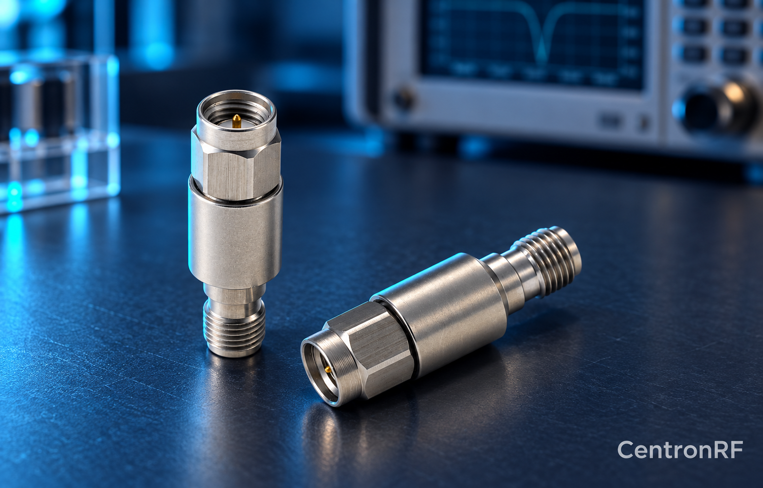
SMA DC block listed for 8 GHz applications. The linked SMA block gives an upper-frequency reference. Confirm its lower passband limit, working voltage, RF power and whether it blocks the inner, outer or both conductors. A catalog range starting with DC should not be interpreted as DC transmission.
Further reading
Mini-Circuits: DC Block Specifications. This background reference explains general principles; the selected Centron RF model’s datasheet governs its own ratings.
Related guides
Educational guide. Numerical examples use the stated assumptions and are not test results for a supplied unit.