


A DC resistance reading cannot characterize frequency-dependent impedance, parasitic effects or high-power thermal behavior. It is only a limited check where the design permits it.
How it works in practice
At RF, the internal structure and connector introduce capacitance and inductance. Use a calibrated reflection measurement to evaluate match at the intended frequencies. A DC-blocked termination may not read its nominal impedance with an ohmmeter, so understand the construction before interpreting the result.
Example and interpretation
A nominal 50-ohm DC reading does not prove low VSWR at 6 GHz.
Checks before use
- Check whether DC continuity is expected
- Measure only while disconnected
- Measure RF return loss
- Confirm power and thermal requirements
Important limit
Do not reject a DC-blocked design solely because an ohmmeter reports an open circuit.
Related Centron RF product
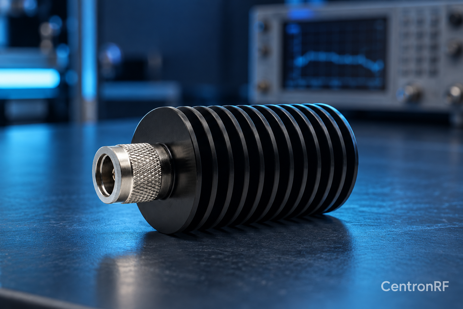
N-type 50 W 6 GHz dummy load. The linked N-type load is a starting point for comparing impedance, bandwidth, power and mechanical fit. Confirm the exact connector option and current thermal conditions before using any load near its rated power.
Further reading
Rohde & Schwarz: VSWR and Return Loss. This background reference explains general principles; the selected Centron RF model’s datasheet governs its own ratings.
Related guides
Educational guide. Numerical examples use the stated assumptions and are not test results for a supplied unit.