


A mismatched load returns part of the incident wave to the source. Distinguish incident, reflected and accepted power when interpreting measurements.
How it works in practice
With suitable directional measurements at one reference plane, accepted power is incident power minus reflected power. Coupler directivity and calibration affect the uncertainty, especially for small reflections. Cable losses between the coupler and load complicate comparisons unless corrected.
Example and interpretation
If incident power is 10 W and reflected power is 0.2 W at the load plane, accepted power is approximately 9.8 W.
Checks before use
- Define one reference plane
- Measure both directions
- Apply coupler corrections
- Check source mismatch tolerance
Important limit
A forward reading alone is not always the power absorbed by the load.
Related Centron RF product
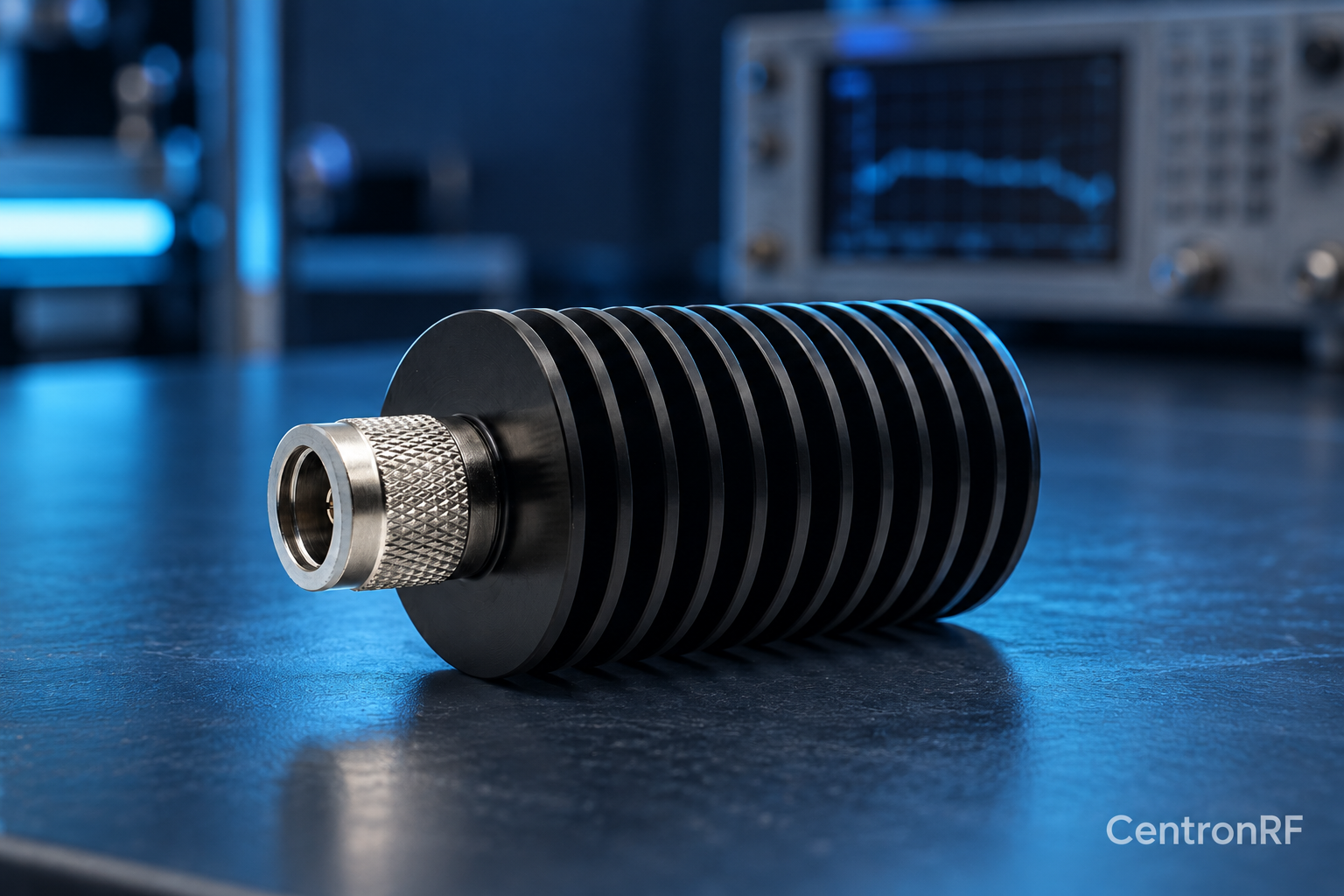
N-type 50 W 6 GHz dummy load. The linked N-type load is a starting point for comparing impedance, bandwidth, power and mechanical fit. Confirm the exact connector option and current thermal conditions before using any load near its rated power.
Further reading
Rohde & Schwarz: VSWR and Return Loss. This background reference explains general principles; the selected Centron RF model’s datasheet governs its own ratings.
Related guides
- Why DC Resistance Does Not Fully Qualify an RF Load
- What to Include in an RF Dummy Load Purchase Request
Educational guide. Numerical examples use the stated assumptions and are not test results for a supplied unit.