


Parasitic capacitance, inductance, connectors and switch paths can make actual attenuation vary with frequency. A dial setting is therefore a nominal value.
How it works in practice
Measure or obtain specified attenuation error at the intended frequency and selected state. A single low-frequency check does not establish performance at the top of the band. When comparing thresholds across frequencies, use the correction for each frequency rather than a constant correction measured elsewhere.
Example and interpretation
A measured 10.1 dB at 100 MHz and 10.6 dB at 5 GHz changes the delivered receiver level by 0.5 dB if left uncorrected.
Checks before use
- Specify test frequencies
- Measure representative states
- Apply state-specific corrections
- Include calibration uncertainty
Important limit
Fine increments do not eliminate frequency-dependent error.
Related Centron RF product
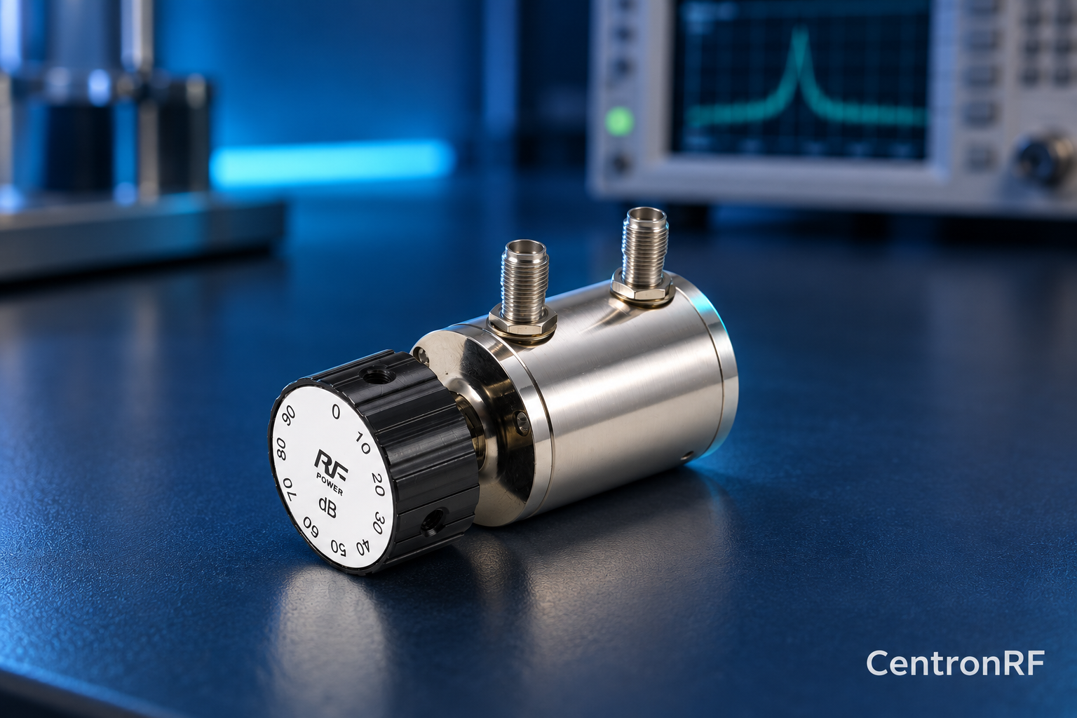
SMA rotary attenuator with 10 dB steps. The linked rotary model lists 0–90 dB adjustment in 10 dB steps, 50-ohm impedance and a DC–6 GHz band. Its listed continuous input is 2 W; obtain explicit switching and pulse limits before applying those stresses.
Further reading
Keysight: Accurate Network Measurements. This background reference explains general principles; the selected Centron RF model’s datasheet governs its own ratings.
Related guides
- Manual Step Attenuator Versus Programmable Attenuator
- Step Attenuators for Receiver Overload Testing
Educational guide. Numerical examples use the stated assumptions and are not test results for a supplied unit.