


A 0 dB setting or through state usually has some insertion loss. It must be characterized if accurate signal levels are required.
How it works in practice
Connectors, contacts and internal transmission structures contribute loss even without deliberate attenuation. In an adjustable unit, every selected state can have different match and loss. Treat the zero setting as a reference state with measurable performance, rather than a physically perfect connection.
Example and interpretation
If the through state measures 0.6 dB loss, a 0 dBm source produces approximately -0.6 dBm before any additional cable loss.
Checks before use
- Measure the through state
- Record frequency and connection conditions
- Include its loss in corrections
- Recheck after a setup change
Important limit
Zero on a dial does not certify zero insertion loss.
Related Centron RF product
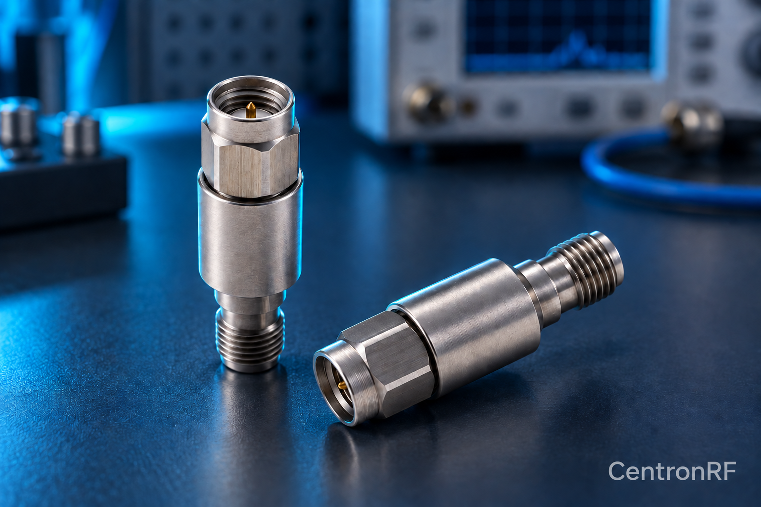
SMA 5 W 6 GHz fixed attenuator. The SMA 5 W model is listed as a 50-ohm fixed attenuator with a DC–6 GHz range. Select an available attenuation option and verify the current tolerance, cooling conditions and pulse limits for your application.
Further reading
Keysight: Spectrum Analysis Basics. This background reference explains general principles; the selected Centron RF model’s datasheet governs its own ratings.
Related guides
- RF Attenuator Versus RF Filter: Which Problem Are You Solving?
- External Versus Internal Spectrum Analyzer Attenuation
Educational guide. Numerical examples use the stated assumptions and are not test results for a supplied unit.