



A microwave radio receiver test is meaningful only when the wanted signal level is known at the receiver’s input reference plane. The signal generator display alone does not include the losses of cables, adapters, attenuators, DC blocks or other fixtures between the source and the receiver.
For communications engineers, a conducted test with controlled attenuation is a useful way to compare receivers and investigate level-dependent behavior. It does not, by itself, reproduce propagation, interference or every condition of a working microwave link. This guide explains how to build an interpretable test and where passive RF accessories affect the result.
Define the receiver result before assembling the RF path
“Sensitivity” needs an associated performance criterion. For a digital radio, record the waveform, channel bandwidth, modulation, coding, data rate, packet length and the error-rate or delivery criterion used for the decision. Also specify the observation period or amount of data. An analog receiver may use a different criterion, such as an audio quality measurement.
Two receivers should not be compared using different waveforms or pass conditions. The same device can produce different thresholds when these conditions change. Rohde & Schwarz’s receiver-testing overview distinguishes wanted-signal sensitivity from tests that also introduce unwanted signals and more demanding conditions.
Draw and label the complete conducted route
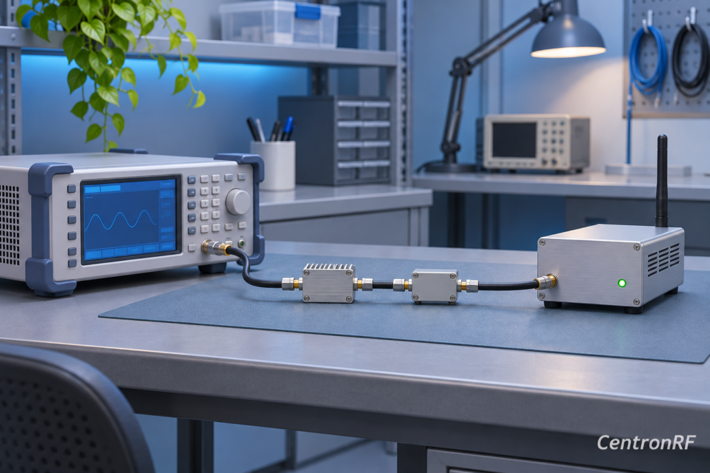
A typical route includes a signal source, cable, level-control components and the receiver input. At an RF or IF port, add any required bias-handling hardware and interface adapters. At a microwave-frequency port, every component must cover that actual band; an accessory suitable for an IF measurement is not automatically suitable at the radio’s microwave carrier frequency.
Mark the receiver input reference plane on the drawing. Label the individual components and any attenuator setting. If an instrument applies a level-offset correction, record whether the displayed value already includes the route loss. Otherwise the same loss can be corrected twice.
Use a level budget with a clear sign convention
For a simple passive route, an initial budget is:
Preceiver (dBm) = Psource (dBm) − Lroute (dB).
Suppose the source setting is −40 dBm and the nominal route contains 1.3 dB cable loss, a 20 dB attenuator, a 0.4 dB DC block and 0.3 dB of adapter loss. The budget gives 22 dB total loss and −62 dBm at the receiver plane. This is a worked calculation, not a measured result or a specification for a CentronRF product.
The next step is to characterize the assembled route at the relevant frequencies, with equipment and methods appropriate to the required uncertainty. Check frequency response and mismatch rather than assuming that a single catalog value applies everywhere. A loss measured at one frequency should not silently become a correction for an entire channel plan.
Keysight’s receiver-calibrator overview illustrates why moving a power reference plane toward the device under test is useful when cables introduce loss. The suitable method for a particular bench depends on its instruments, interfaces and required accuracy.
Choose attenuation for range, resolution and repeatability
A fixed attenuator can establish part of the level range, while a variable attenuator allows controlled level changes. Important properties include operating band, insertion loss at the reference setting, attenuation accuracy, step size, repeatability, power rating and match. Connector and enclosure choices also affect how consistently the route can be assembled.
Use smaller level steps near the pass/fail transition when that improves the resolution of the result. Repeat points around the transition to distinguish a stable threshold from a statistical outcome. Record the actual setting and correction used rather than treating the nominal knob marking as the complete uncertainty statement.
The RF attenuator range provides examples of the different connector, power and control formats available for passive level management. Select against the bench requirement; adding an attenuator does not make every connected instrument immune to overload.
Place DC blocks according to the actual bias path
Some communications interfaces carry DC along the coax to power an active device. Before adding a DC block, identify where the DC originates, which branch needs it and which instrument input must not receive it. Interrupting the wanted bias feed can make an otherwise correct RF test fail because the active device is no longer powered.
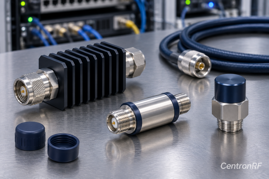
A DC block has an operating band and voltage rating, and may introduce additional loss and phase variation. It is not a general substitute for an isolator, surge protector or power limiter. Its behavior must be included in the route characterization. Anritsu’s DC-block description explains the basic function of passing an AC signal while excluding DC components; exact ratings remain part specific.
Control noise, leakage and unwanted signals separately
When testing near a receiver’s threshold, the wanted carrier is only one part of the input condition. Consider source noise, unwanted emissions, leakage around the intended conducted route and the receiver’s own operating state. A high-attenuation setting does not prove that all energy arriving at the receiver has passed through that attenuator.
A passive attenuator placed ahead of a receiver also changes the system noise behavior. Under the usual matched, reference-temperature approximation, its loss adds to the noise figure of the following receiver. This matters when interpreting a measurement of the receiver-plus-pad combination rather than the receiver alone.
If investigating blocker tolerance or coexistence, define a separate test with the relevant unwanted signal, combining network and calibration. Lowering the wanted signal through a single passive route is not a replacement for that experiment.
Connect the bench result to a real microwave link carefully
Controlled attenuation helps quantify how the radio behaves as conducted input level changes under a stated waveform. A field link additionally depends on antenna alignment, feeder losses, propagation, interference, weather and installation conditions. Static attenuation does not recreate frequency-selective fading or a time-varying channel.
Keep the conducted threshold result, the link-budget assumptions and field observations as distinct records. Compare them only after aligning bandwidth, waveform and reference-plane definitions. This makes it easier to determine whether an apparent margin change belongs to the radio, the test fixture or the installation.
Common questions
Is generator output equal to receiver input power?
Only when the intervening route loss and any applied corrections have been accounted for appropriately.
Can a DC block be added without updating the correction?
No. Its RF response and its effect on the bias arrangement must be checked before treating the resulting measurement as equivalent.
Does a conducted sensitivity test prove a link will meet its field availability target?
No. It establishes radio behavior under the defined bench conditions; link availability also requires suitable propagation and installation analysis.
Related reading: checking the coaxial DC path for a block downconverter.
Leave a Reply