


High attenuation requires sufficient dynamic range, low leakage and a suitable noise floor. A displayed value near the floor may be only a limit.
How it works in practice
Characterize the setup with appropriate terminations and controlled source changes. Improve shielding and averaging where the method permits. Do not report a precise attenuation when the transmitted signal is unresolved. State a bound or uncertainty consistent with the instrument capability.
Example and interpretation
If the setup cannot resolve below a level corresponding to 70 dB loss, it cannot directly confirm an exact 90 dB value.
Checks before use
- Measure the floor
- Check leakage
- Adjust the method safely
- Report supported limits
Important limit
A numerical display does not guarantee the signal is distinguishable from noise.
Related Centron RF product
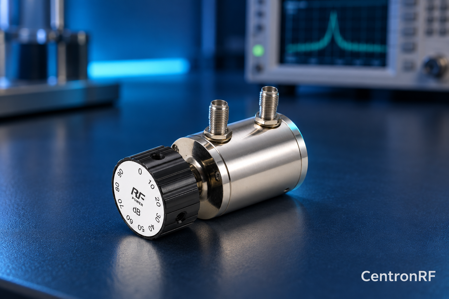
SMA rotary attenuator with 1 dB steps. The linked fine-step unit lists 0–10 dB in 1 dB increments. It can be considered for controlled level changes within its ratings. Dial resolution does not establish traceable accuracy; calibrate the assembled path as required.
Further reading
Keysight: Fundamentals of RF and Microwave Power Measurements. This background reference explains general principles; the selected Centron RF model’s datasheet governs its own ratings.
Related guides
Educational guide. Numerical examples use the stated assumptions and are not test results for a supplied unit.