


A reference plane is the location where a measured or calibrated quantity is defined. It determines which cables and accessories are included in the result.
How it works in practice
State whether power is reported at the source connector, after a cable or at the device input. Calibration can move the effective measurement plane when the method supports it. Components added beyond that plane need appropriate correction. This avoids comparing levels defined at different physical locations.
Example and interpretation
A −10 dBm reading at an instrument connector does not necessarily mean −10 dBm at a device beyond a lossy cable.
Checks before use
- Choose the measurement location
- Document included components
- Calibrate appropriately
- Apply remaining path corrections
Important limit
Do not compare measurements without checking their reference planes.
Related Centron RF product
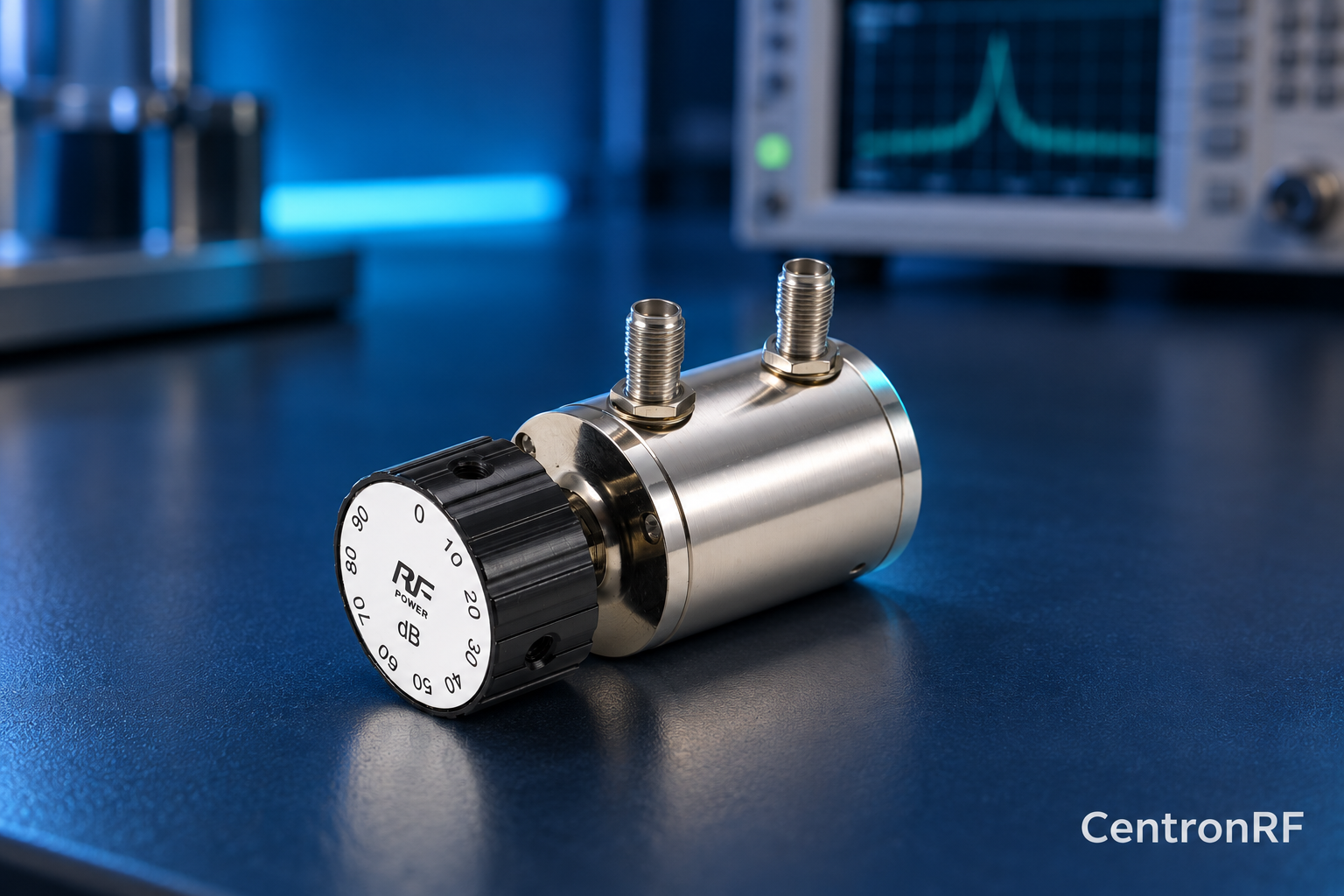
SMA rotary attenuator with 1 dB steps. The linked fine-step unit lists 0–10 dB in 1 dB increments. It can be considered for controlled level changes within its ratings. Dial resolution does not establish traceable accuracy; calibrate the assembled path as required.
Further reading
Keysight: Fundamentals of RF and Microwave Power Measurements. This background reference explains general principles; the selected Centron RF model’s datasheet governs its own ratings.
Related guides
Educational guide. Numerical examples use the stated assumptions and are not test results for a supplied unit.