


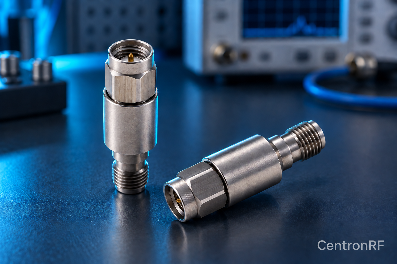
Choose component interfaces and cable ends together to reduce unnecessary transitions. Fewer adapters can simplify loss, matching and mechanical support.
How it works in practice
Start with a drawing showing each port's impedance and gender. Select rated assemblies that connect directly where practical. Keep necessary transitions documented and calibrated. Convenience should not override safe power or connector compatibility.
Example and interpretation
A cable made with SMA on one end and N-type on the other can avoid a rigid adapter chain when its ratings suit the path.
Checks before use
- List every interface
- Select compatible cable ends
- Minimize redundant transitions
- Verify complete path performance
Important limit
Do not remove a needed impedance transition just to reduce part count.
Related Centron RF product
N-type fixed attenuator for a compatible RF path. Use a product page to check both connector interfaces, nominal impedance and model-specific band and power requirements. The connector family alone cannot establish a component’s total RF capability.
Further reading
Rohde & Schwarz: Impedance, VSWR and Return Loss. This background reference explains general principles; the selected Centron RF model’s datasheet governs its own ratings.
Related guides
Educational guide. Numerical examples use the stated assumptions and are not test results for a supplied unit.