


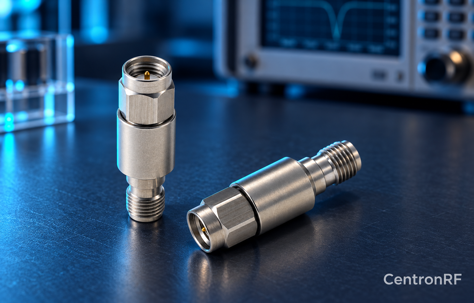
Place the block where it interrupts the unwanted DC path before that DC reaches the protected device. Verify that required bias still reaches the intended powered component.
How it works in practice
Draw both RF and DC routes, including tees, adapters, attenuators and instrument inputs. Consider the block's RF power exposure and whether other parts need DC isolation as well. Include it in the appropriate calibration path so its loss is handled consistently.
Example and interpretation
In a biased-amplifier test, a block between the combined output and an RF-only receiver can protect the receiver while the amplifier retains its intended bias.
Checks before use
- Map all DC paths
- Identify protected ports
- Rate the chosen location
- Calibrate the installed RF path
Important limit
An attenuator elsewhere in the chain does not automatically stop DC.
Related Centron RF product
SMA DC block listed for 8 GHz applications. The linked SMA block gives an upper-frequency reference. Confirm its lower passband limit, working voltage, RF power and whether it blocks the inner, outer or both conductors. A catalog range starting with DC should not be interpreted as DC transmission.
Further reading
Mini-Circuits: DC Block Specifications. This background reference explains general principles; the selected Centron RF model’s datasheet governs its own ratings.
Related guides
Educational guide. Numerical examples use the stated assumptions and are not test results for a supplied unit.