


A fixed pad can reduce the power entering a rotary attenuator and extend total attenuation. Its placement must be chosen from the full power and thermal budget.
How it works in practice
Put a suitable high-power fixed pad upstream when the rotary unit cannot tolerate the source. Calculate the fixed pad's dissipated power and the remaining rotary input. Check startup peaks, not only steady-state averages. Extra pads also reduce available signal at the receiver and add uncertainty.
Example and interpretation
A 10 W source through a suitably rated 20 dB pad reaches the rotary unit at about 0.1 W, while the fixed pad dissipates about 9.9 W.
Checks before use
- Calculate maximum source power
- Rate the upstream pad
- Check rotary input and pulses
- Calibrate combined attenuation
Important limit
A small downstream pad cannot protect an overloaded upstream switch.
Related Centron RF product
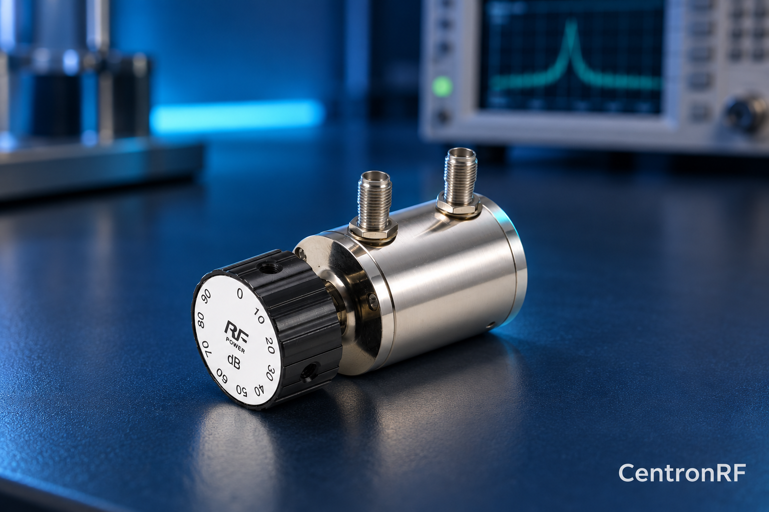
SMA rotary attenuator with 10 dB steps. The linked rotary model lists 0–90 dB adjustment in 10 dB steps, 50-ohm impedance and a DC–6 GHz band. Its listed continuous input is 2 W; obtain explicit switching and pulse limits before applying those stresses.
Further reading
Keysight: Accurate Network Measurements. This background reference explains general principles; the selected Centron RF model’s datasheet governs its own ratings.
Related guides
Educational guide. Numerical examples use the stated assumptions and are not test results for a supplied unit.