


For a two-dial attenuator, use the documented attenuation table to determine how settings combine. Product names alone do not establish the electrical topology.
How it works in practice
Series and parallel wording may describe a product arrangement or internal implementation. Confirm the actual state table, minimum insertion loss and per-state power limits. If two independently cascaded pads are involved, nominal losses add in dB, but do not assume that rule applies to every named parallel unit.
Example and interpretation
Two cascaded sections set to 20 dB and 7 dB produce nominally 27 dB of selected attenuation before baseline losses.
Checks before use
- Obtain the state table
- Identify how the controls interact
- Confirm power limits
- Verify a few representative states
Important limit
Do not infer a circuit diagram from a catalog label.
Related Centron RF product
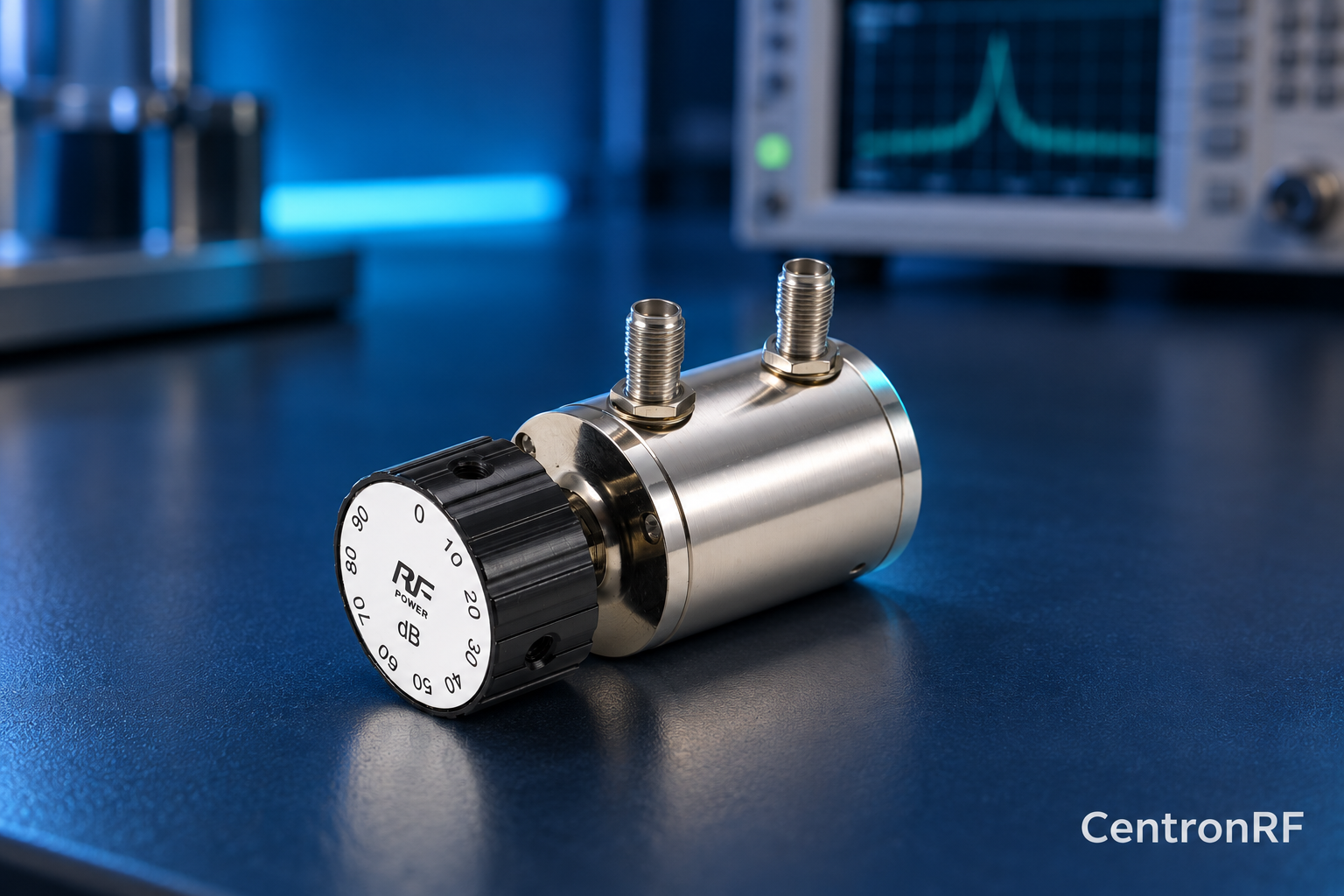
SMA rotary attenuator with 10 dB steps. The linked rotary model lists 0–90 dB adjustment in 10 dB steps, 50-ohm impedance and a DC–6 GHz band. Its listed continuous input is 2 W; obtain explicit switching and pulse limits before applying those stresses.
Further reading
Keysight: Accurate Network Measurements. This background reference explains general principles; the selected Centron RF model’s datasheet governs its own ratings.
Related guides
Educational guide. Numerical examples use the stated assumptions and are not test results for a supplied unit.