


Use a step attenuator to lower a known RF input in controlled increments while measuring an explicitly defined receiver performance metric.
How it works in practice
Start with a source level that the receiver can safely tolerate after total path loss. Record frequency, modulation, bandwidth and the pass criterion. Increase attenuation until the receiver fails that criterion, then repeat near the transition using smaller steps. Correct for cable loss and calibrated attenuation.
Example and interpretation
If a source delivers −20 dBm and the measured path loss is 60 dB, the receiver input is approximately −80 dBm in a matched setup.
Checks before use
- Define a packet-error or detection criterion
- Calibrate path loss
- Sweep and log each state
- Repeat near the transition
Important limit
Receiver sensitivity cannot be inferred from a dial reading without knowing the source level and path loss.
Related Centron RF product
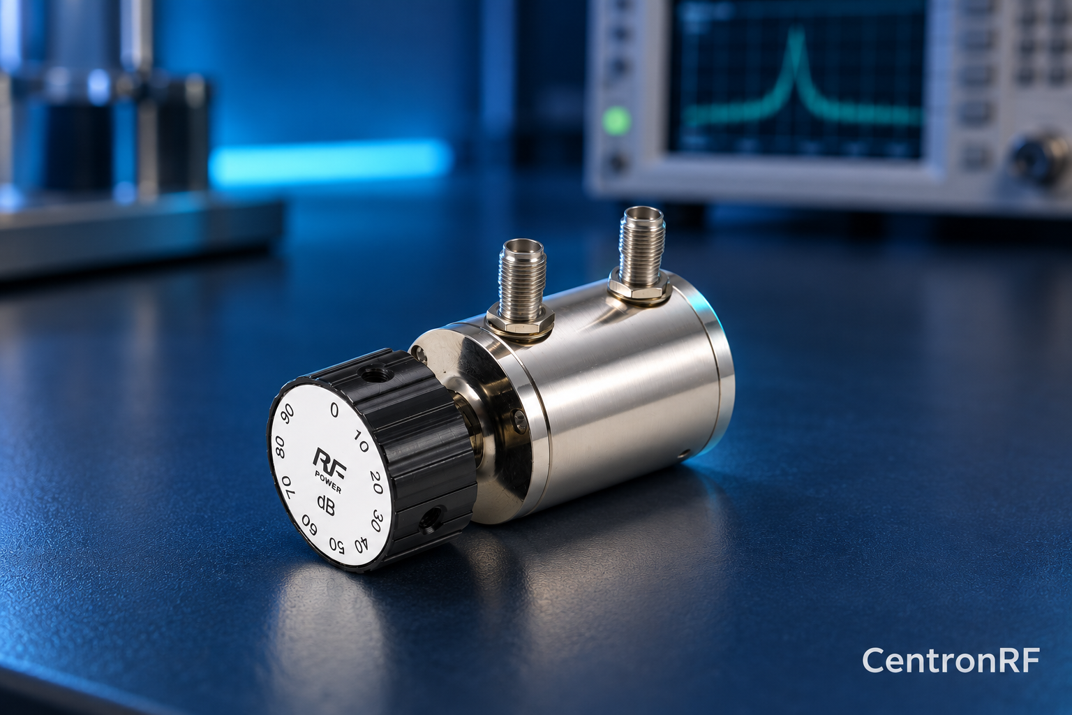
SMA rotary attenuator with 10 dB steps. The linked rotary model lists 0–90 dB adjustment in 10 dB steps, 50-ohm impedance and a DC–6 GHz band. Its listed continuous input is 2 W; obtain explicit switching and pulse limits before applying those stresses.
Further reading
Keysight: Accurate Network Measurements. This background reference explains general principles; the selected Centron RF model’s datasheet governs its own ratings.
Related guides
- How to Establish the Zero Reference of a Step Attenuator
- Rotary Attenuator Repeatability: How to Check It
Educational guide. Numerical examples use the stated assumptions and are not test results for a supplied unit.